
Flexible double-valve

A beer keg and beer technology, applied in liquid distribution, packaging, distribution devices, etc., can solve the problems of time-consuming and troublesome, and achieve the effect of increasing the sealing ability

Inactive Publication Date: 2010-03-24
麦克罗-马迪克有限公司
View PDF0 Cites 2 Cited by
  • Summary
  • Abstract
  • Description
  • Claims
  • Application Information

AI Technical Summary

Problems solved by technology

This has the disadvantage of being time consuming, cumbersome, and having to dismantle the fluid handling system each time the seal needs to be cleaned
[0009] Another way to overcome microbial growth problems is to instruct users of fluid handling systems to frequently replace seals and other critical components of the system, thereby limiting the time allowed for growth of bacteria etc.
This has the disadvantage that execution of the order to replace the seal is dependent on the morale and competence of the user of the fluid handling system

Method used


Image

  • Flexible double-valve
  • Flexible double-valve
  • Flexible double-valve

Examples


Embodiment Construction

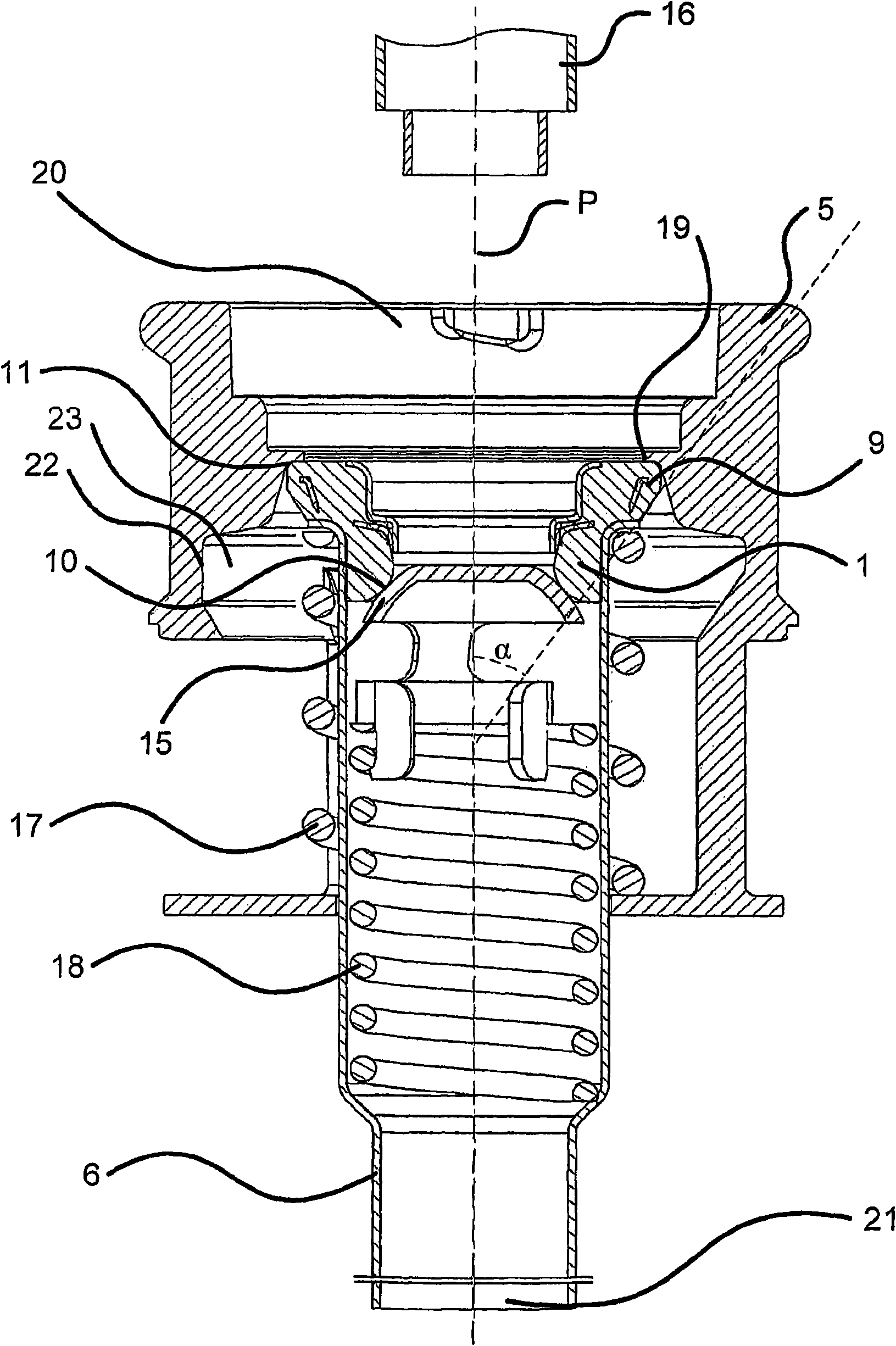
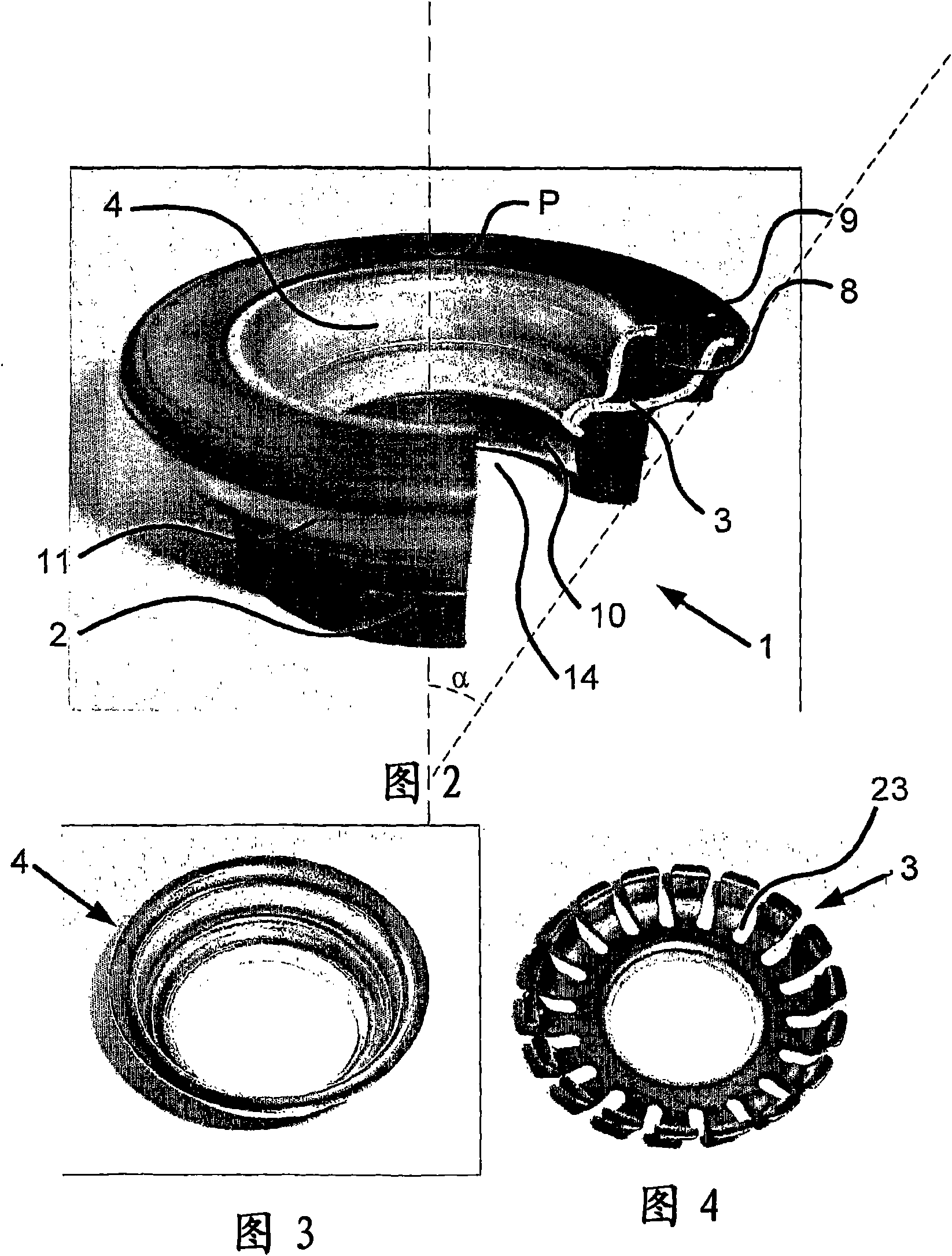
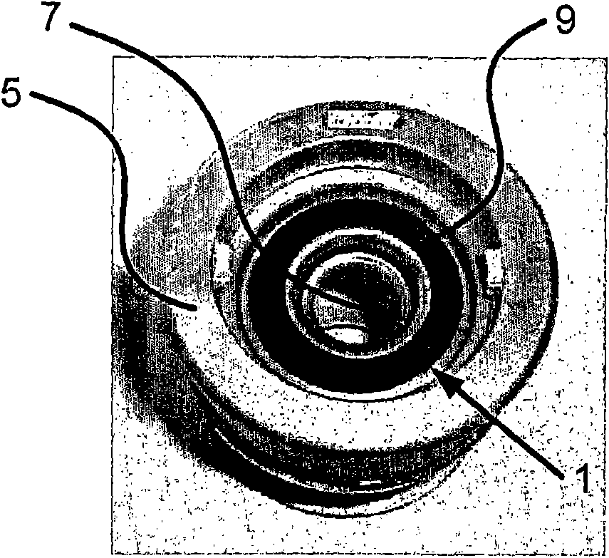
[0032] figure 1 shown inserted into the exemplary fluid pathway 7 (in figure 1A cross-sectional view of a preferred embodiment of the sealing device 1 of the invention not shown in ). The fluid passage 7 is formed by a connection 5 for a beer keg 13 (not shown). Surrounded by the connection piece 5 , the fluid passageway 7 extends from the top 20 of the connection piece 5 along the central axis P of the connection piece 5 to the bottom 21 of the connection piece 5 , allowing fluid to flow through the connection piece 5 . The circumference of the fluid passage tapers from the top 20 of the connector to the opening 19 . From the opening 19 to about the middle part 22 of the connecting part 5, the fluid channel 7 gradually widens, and from about the middle part 22 of the connecting part 5 to the bottom 21 of the connecting part 5, the circumference of the fluid channel 7 gradually becomes smaller. Inserting the sealing device 1 into the middle part 22 of such a connection 5 is...


PUM


Abstract

The present invention relates to a sealing device for mounting in a fluid passage of a connection piece such as beer extractor tube for a beer keg characterised in that the sealing device is adapted to be permanently-deformed when it is removed from said fluid passage.

Description

technical field [0001] The present invention relates to a sealing device for installation in the fluid passage of a connection, such as a beer extractor conduit for a beer keg. Background technique [0002] Sealing of fluid pathways finds widespread use in fluid handling systems that store, transport, distribute, or utilize fluids. Examples include beverage dispensing systems, hydraulic systems, refrigeration systems, heating systems, sanitary systems, etc. In some examples, the fluid exists in a liquid state, while in other examples the fluid exists in a gaseous state, and in other examples the fluid changes state in the system. Some systems are designed to handle a single fluid type, while others are designed to handle different fluid types simultaneously, and in some cases the different types of fluids even exist in different forms. Clearly, due to the multitude of applications and the variety of fluid types and configurations, there are certain requirements for sealing...

Claims


Application Information

Patent Timeline
Patent Type & Authority Applications(China)
IPC IPC(8): B67D1/08
CPCB67D1/0847B67D1/0838B67D1/0831
Inventor K·里斯
Owner 麦克罗-马迪克有限公司
Learn More