
Cylindrical shape automatic riveted-joint apparatus

A riveting device and cylindrical technology, applied in the field of pressure screens, can solve the problems of welding heating, affecting product accuracy, micro-deformation, etc., and achieve the effects of high work efficiency, product accuracy, and riveting speed.

Inactive Publication Date: 2011-11-09
赵仁理
View PDF0 Cites 0 Cited by
  • Summary
  • Abstract
  • Description
  • Claims
  • Application Information

AI Technical Summary

Problems solved by technology

[0002] At present, when manufacturing pressure screens at home and abroad, most of the U-shaped rings of the screen drum and the screen bars are welded together. The disadvantage is that welding heating causes slight deformation, which affects product accuracy.

Method used


Image

  • Cylindrical shape automatic riveted-joint apparatus
  • Cylindrical shape automatic riveted-joint apparatus

Examples


Embodiment Construction

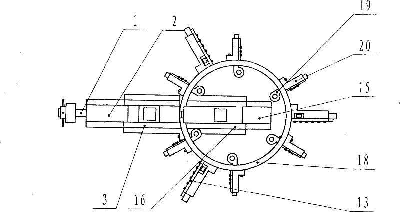
[0010] Refer to attached figure 1 , 2 , it includes a two-way screw 1, the two-way screw 1 and the positioning block nut 2 form a transmission pair, the positioning block nut 2 is installed on the guide rail 3, the guide rail 3 is fixed on the positioning block nut bracket 23, and the positioning block nut bracket 23 is fixed on the outer wall of the main body 18 of the cylindrical riveting device, the positioning block guide rail 4 is equipped with the positioning block nut 2, and several positioning blocks 5 are installed on the positioning block guide rail 4, and the steam riveting gun screw nut 15 is installed on the steam riveting gun guide rail 16, the steam riveting gun guide rail 16 is installed on the steam riveting gun nut bracket 17, and the steam riveting gun screw nut bracket 17 is fixed on the inner wall of the riveting device main body 18, and the steam riveting gun screw nut 15 and the two-way lead screw 1 form a transmission pair , steam riveting gun position...


PUM


Abstract

The present invention provides a cylindrical shape automatic riveted-joint apparatus which riveted joints a screen drum U-shaped loop with a screen bar in manufacturing a pressure screen. The apparatus is mainly used for solving problem of micro deformation caused by welding the screen drum U-shaped loop with the screen bar in the prior art. The apparatus comprises a transmission pair composed bya bidirectional leading screw and a positioning block nut, the positioning block nut is fixed on an outer wall of a main body through a guide rail and a support, a positioning block guide rail and a positioning block are arranged on the positioning block nut, a pneumatic-rivet gun nut is fixed on an inner wall of the main body through the guide rail and the support, the pneumatic-rivet gun nut and the bidirectional leading screw comprise the transmission pair, the pneumatic-rivet gun is arranged on the pneumatic-rivet gun nut through the pneumatic-rivet gun positioning block and the guide rail; an U-shaped loop positioning rule holder is arranged on the outer wall of the main body of the riveted-joint apparatus, an U-shaped loop limiter is arranged on the U-shaped loop positioning rule holder through the U-shaped loop positioning rule and a slide block, the U-shaped loop limiter is arranged on a slide block holder of an U-shaped loop limiting pile through the U-shaped loop limiting pile and the slide block. The apparatus has advantages of processing circumference riveted joint automatically and no deformation.

Description

Technical field: [0001] The invention relates to a device for riveting a U-shaped ring of a screen drum and a screen bar when manufacturing a pressure screen for papermaking equipment. Background technique: [0002] At present, when manufacturing pressure screens at home and abroad, the U-shaped ring of the screen drum and the screen bars are mostly welded together. The disadvantage is that welding heating causes slight deformation, which affects product accuracy. Invention content: [0003] The technical problem to be solved by the present invention is to provide a cylindrical automatic riveting device for riveting the U-shaped ring of the screen drum and the screen bars together when manufacturing the pressure screen. [0004] The purpose of the present invention is achieved in this way: it includes a two-way lead screw, the two-way lead screw and the positioning block nut form a transmission pair, the positioning block nut is installed on the guide rail, the guide rail ...

Claims


Application Information

Patent Timeline
Patent Type & Authority Patents(China)
IPC IPC(8): B21J15/14B21J15/38
Inventor 赵仁理
Owner 赵仁理
Learn More