Double-row tilting directional microporous end surface no-leakage mechanical sealing structure

A mechanical seal and directional technology, applied in the direction of engine seals, mechanical equipment, engine components, etc., can solve the problems of solid particle resistance, limited fluid dynamic pressure effect, poor sealing reliability, short service life, etc., to improve the performance of fluid Dynamic pressure effect and tightness, prolonging service life, enhancing the effect of hydrodynamic pressure effect

Active Publication Date: 2013-06-05
ZHEJIANG UNIV OF TECH
View PDF0 Cites 0 Cited by
  • Summary
  • Abstract
  • Description
  • Claims
  • Application Information

AI Technical Summary

Problems solved by technology

[0003] In order to overcome the limited anti-solid particle ability and fluid dynamic pressure effect of the seal in the prior art, the start-stop effect is poor under low pressure conditions, and the service life is short, especially for medium containing solid particles, gas medium and easy to crystallize and vaporize In the case of toxic and highly polluting media, the sealing reliability is poor. The invention provides a medium that can be applied to various conditions, which enhances the ability to prevent solid particles, hydrodynamic pressure effect and sealing performance, and fully utilizes the micropore end surface. The advantage of reducing wear makes the seal start and stop effect good, high reliability, zero leakage, long life double-row inclined directional micro-hole end face leak-free mechanical seal structure

Method used


Image

  • Double-row tilting directional microporous end surface no-leakage mechanical sealing structure
  • Double-row tilting directional microporous end surface no-leakage mechanical sealing structure
  • Double-row tilting directional microporous end surface no-leakage mechanical sealing structure

Examples


Embodiment Construction

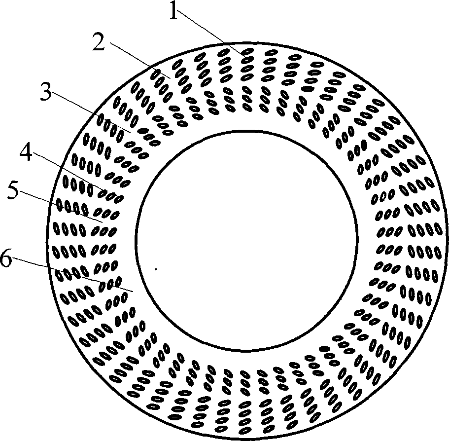
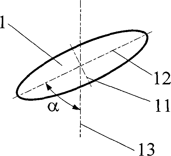
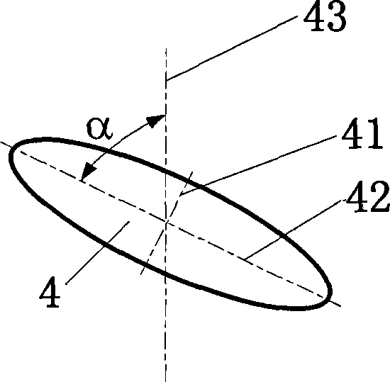
[0019] refer to Figure 1-4 , a double-row inclined directional microporous end face non-leakage mechanical seal structure, including a moving ring 7 and a static ring 8 of the mechanical seal, one side of the end faces of the moving ring 7 and the static ring 8 is the high pressure side, that is, the upstream, The other side of the end faces of the moving ring 7 and the static ring 8 is the low-pressure side, that is, the downstream side, and the end faces of the moving ring 7 or the static ring 8 are provided with outer and inner microporous rings 2,5, and the outer and inner The micropore 1,4 major axis 12,42 of the microporous annulus 2,5 is opposite to the inclination angle direction of the sealing end face diameter 13,43 passing through the micropore 1,4 center; the outer and inner microporous annulus 2 , 5 are arranged on the upstream and downstream of the end face respectively, and a continuous annular sealing dam 3, 6 is provided between the outer and inner microporou...


PUM


Abstract

The invention relates to a double-row tilting directional microporous end surface no-leakage mechanical sealing structure, comprising a dynamic ring and a static ring which are sealed mechanically, wherein one side of the end surface of the dynamic ring or the static ring is an high-voltage side, namely an upstream part, and the other side thereof is a low-voltage side, namely an downstream part,the end surface of the dynamic ring or the static ring is provided with an outer microporous ring belt and an inner microporous ring belt; microporous long shafts of the outer microporous ring belt and the inner microporous ring belt are opposite to the direction of a tilting angle of the diameter of the sealing end surface passing through the center of the micropore; the outer microporous ring belt and the inner microporous ring belt are respectively arranged on the upstream part and the downstream part of the end surface; and a continuous ring-shaped sealing dam are respectively arranged between the outer microporous ring belt and the inner microporous ring belt and the downstream part of the inner microporous ring belt. The mechanical sealing structure has the beneficial effects of: realizing no contact, wear resistance and no leakage of sealing, prolonging the service life and improving the sealing reliability.

Description

technical field [0001] The patent of the present invention relates to the technical field of end face mechanical seal structure design, specifically refers to the double-row inclined directional microporous end face non-leakage mechanical seal structure, which is suitable for shaft end seals of rotating shafts of various compressors, pumps, and kettle agitators. device. Background technique [0002] Mechanical seals are the main means to prevent shaft end leakage of rotary fluid machinery. With the rapid development of petrochemical and other industries, mechanical seals are required to develop with high parameters, higher stability and reliability and longer service life, and Toxic, flammable and explosive gases require strict control of their leakage. At present, the end face forms that realize the non-contact mechanical seal mainly include one-way spiral groove, one-way herringbone spiral groove, one-way Y-shaped spiral groove, one-way L-shaped spiral groove, one-way arc...

Claims


Application Information

Patent Timeline
Patent Type & Authority Patents(China)
IPC IPC(8): F16J15/16F16J15/40
CPCF16J15/3424
Inventor 白少先彭旭东盛颂恩孟祥铠
Owner ZHEJIANG UNIV OF TECH
Why Eureka
Try Eureka