Foundation pile

A technology of foundation pile and pile body, which is applied in sheet pile wall, foundation structure engineering, construction, etc., can solve the problems of increasing construction volume and cost, and achieve the effect of reducing the number of piles, expanding the contact area, and reducing the construction volume.

Inactive Publication Date: 2010-03-17
高荣江
View PDF0 Cites 12 Cited by
  • Summary
  • Abstract
  • Description
  • Claims
  • Application Information

AI Technical Summary

Problems solved by technology

This will increase the construction volume and cost

Method used


Image

  • Foundation pile
  • Foundation pile
  • Foundation pile

Examples


Embodiment Construction

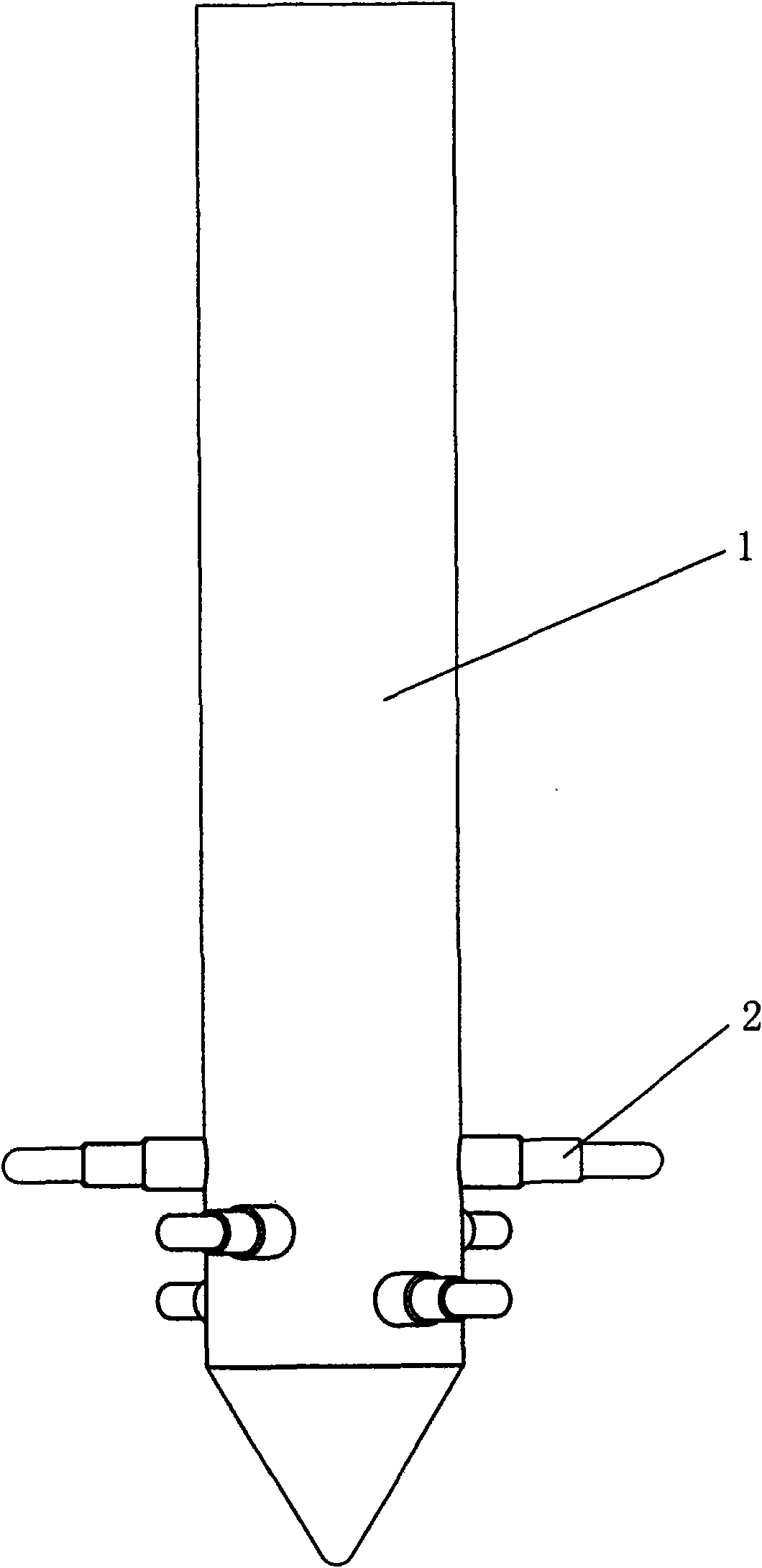
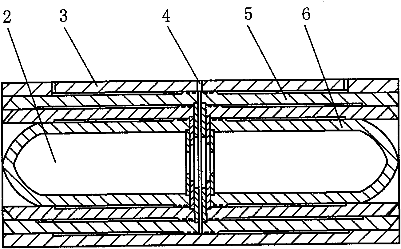
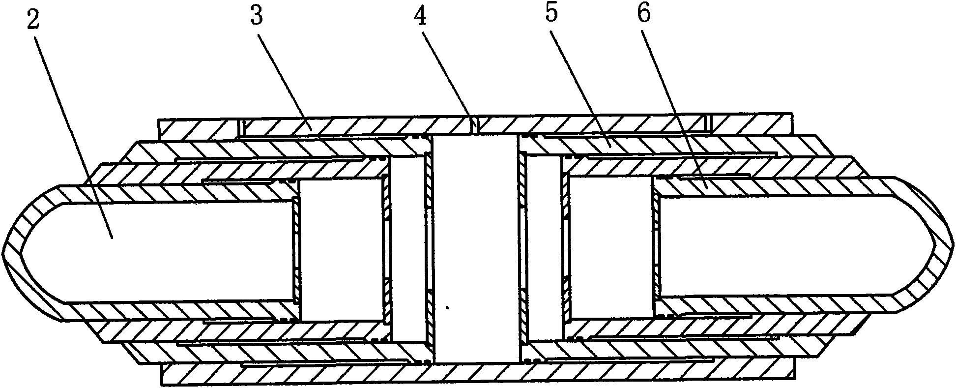
[0010] Foundation pile of the present invention is made of pile body 1 and two-way multi-stage jack 2; Pile body 1 is cylindrical, and the bottom is conical; 2 to 4 two-way multi-stage jacks 2 are housed in the bottom of pile body 1, and its The installation angles are staggered from each other. The two-way multi-stage jack 2 is composed of a casing 3 and two sets of symmetrical movable cylinders 5 and 6; there is a hydraulic oil inlet 4 in the middle of the casing; the movable cylinders 5 and 6 are divided into three stages, which are set together and symmetrically mounted on the casing within 3.


PUM


Abstract

The invention provides a foundation pile, relating to the foundation pile which is used under bridges and buildings. The foundation pile in the invention is composed of a pile body and a bidirectionalmulti-level jack, wherein, the pile body is in a cylinder shape and the lower part is in a conical shape; and the lower part of the pile body is provided with one to a plurality of bidirectional multi-level jack and the installation angles thereof are staggered mutually. When in use, the bidirectional multi-level jacks are recoiled inside the pile body; the pile body is driven underground througha pile driver, and then a hydraulic pump leads the bidirectional multi-level jack to push out of the pile body and stretch into a foundation layer laterally. By utilizing the bidirectional multi-level jack, the foundation pile expands the contact area between the foundation pile and the foundation, thus having stronger compressive resistance and pull-out resistance; in addition, the foundation pile has simple construction, reliable performance, no earth volume and no pollution, and can greatly reduce the number of piling and construction volume and reduce cost effectively.

Description

technical field [0001] A foundation pile relates to foundation piles used under bridges and buildings. Background technique [0002] Most of the foundation piles used under bridges or buildings are cylindrical steel piles at present. The surface of the cylindrical steel pile is smooth, and the friction with the foundation is small, so its compressive and pull-out resistance are relatively small. In order to overcome this deficiency, it is necessary to overcome multiple piles. This will increase the construction volume and cost. Contents of the invention [0003] The purpose of the present invention is to provide a foundation pile with good compression and pullout resistance. [0004] The foundation pile of the present invention is composed of a pile body and two-way multi-stage jacks; the pile body is cylindrical, and the lower part is conical; one to several two-way multi-stage jacks are arranged at the bottom of the pile body, and their installation angles are mutuall...

Claims


Application Information

Patent Timeline
Patent Type & Authority Applications(China)
IPC IPC(8): E02D5/24E02D5/54E02D5/48
Inventor 高荣江
Owner 高荣江
Why Eureka
Try Eureka