
Packaging case for electro-optical device product, and its manufacturing method

A technology of electron optics and manufacturing methods, which is applied in the direction of electrical equipment casings/cabinets/drawers, electrical components, casings/cabinets/drawer parts, etc., which can solve the problems of labor and working hours, poor production pass rate, and unsatisfactory production. To improve the strength, improve the design, and ensure the strength of impact resistance in order to solve problems such as waterproof

Inactive Publication Date: 2010-03-10
IWATA ELECTRIC WORKS
View PDF1 Cites 7 Cited by
  • Summary
  • Abstract
  • Description
  • Claims
  • Application Information

AI Technical Summary

Problems solved by technology

[0007] Therefore, in the past, after making the two members of the metal shell and the frame member in different ways, the frame member must be installed along the inner side of the erected peripheral wall of the metal shell, and since it needs to be fixed by spot welding, etc., there are not only costs Problems of labor and working hours, poor production pass rate and high cost
[0008] In addition, in the conventional exterior case, the locking claws at several corresponding important parts of the metal case are simply fitted and locked with the locking recesses provided at several important parts on the peripheral surface of the main body case. Due to the fixed structure, not only the metal case may come off due to impact such as falling, but also there is a problem that waterproofness cannot be obtained.

Method used


Image

  • Packaging case for electro-optical device product, and its manufacturing method
  • Packaging case for electro-optical device product, and its manufacturing method
  • Packaging case for electro-optical device product, and its manufacturing method

Examples


Embodiment Construction

[0047] Hereinafter, embodiments of the present invention will be described in detail with reference to the drawings as appropriate.

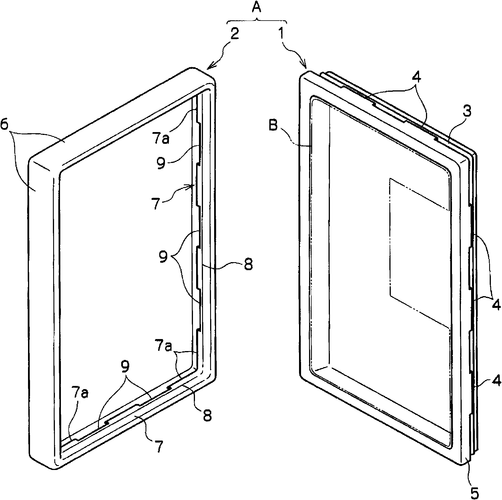
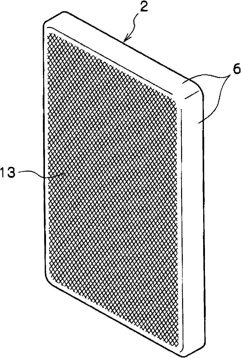
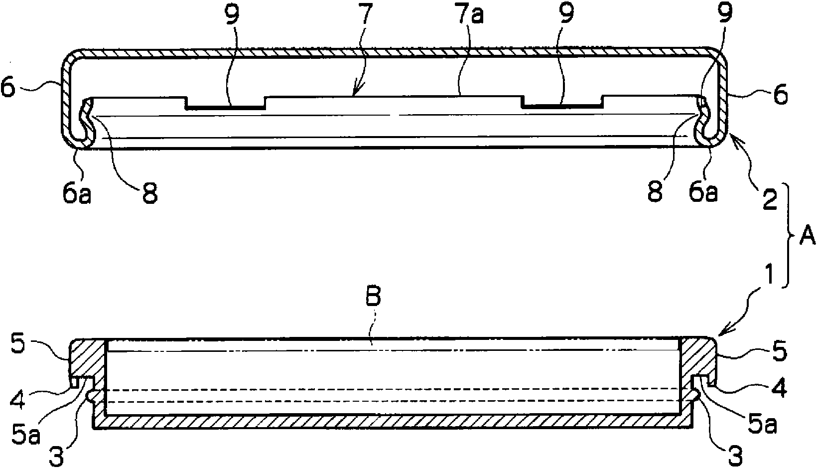
[0048] figure 1 It is each perspective view which shows the state when the main body case and metal case which comprise the exterior case for electro-optical-device products concerning 1st Embodiment are seen from inside, figure 2 It is a perspective view showing the state when only the metal case is viewed from the outside (surface side), image 3 is a cross-sectional view showing the main body case and the metal case, respectively, Figure 4 It is a cross-sectional view showing a state in which a metal case is superimposed and mounted on the main body case by means of an overlay.

[0049] Structure of the exterior case of the first embodiment

[0050] Such as figure 1 As shown, the exterior case A includes: a main body case 1 assembled and built with a substrate B mounted with electronic components;

[0051] The structure of the ma...


PUM


Abstract

Provided is a packaging case for an electro-optical device product, which can be manufactured by a series of pressing operations so that it can be expected to reduce the cost and which can not only differentiate the durability and the textures but also have a water resistance. The packaging case (A) is constituted by overlapping a body case (1) having a fitting ridge (3) on its periphery and a metal case (2) to be fitted on the periphery of the body case (1). The metal case (2) includes a rising peripheral wall (6) formed by pressing a single sheet of metal, and an elastic member portion (7) formed by folding it back from the folded portion (6a) of the rising peripheral wall (6) along the inner side of the rising peripheral wall (6). The elastic member portion (7) is so formed by undulating it as to have a fitting trough (8) to be closely fitted on the fitting ridge (3) of the body case (1).A pattern (13) is formed on the surface of the metal case (2) by a rolling roll (D).

Description

technical field [0001] The present invention relates to an exterior casing constituting casings of electronic optical equipment products such as mobile phones, digital video cameras, portable audio equipment, portable game machines, and electronic notebooks, and a manufacturing method thereof. Background technique [0002] In order to ensure the durability and recycling of products, in recent years, the exterior casings of electro-optical equipment products such as mobile phones, portable audio equipment, and digital cameras have shown a tendency to use mostly metal materials (for example, Refer to Patent Document 1). Image 6 and Figure 7 An example of these is shown. [0003] Such as Image 6 As shown, the exterior case A1 of the existing product has a main body case 100 and a metal case 200. The main body case 100 is formed of a synthetic resin material and is used to house a substrate B on which electronic components are mounted. 200 is installed on the main body casi...

Claims


Application Information

Patent Timeline
Patent Type & Authority Applications(China)
IPC IPC(8): H05K5/02
CPCH05K5/061H05K5/063H05K5/04
Inventor 中本胜也
Owner IWATA ELECTRIC WORKS
Learn More