
Driving device for liquid crystal display

A liquid crystal display and drive device technology, applied to static indicators, instruments, multiple input and output pulse circuits, etc., can solve the problems of clock signal noise of the drive circuit, abnormal display screen, shift register output error pulse signal, etc.

Inactive Publication Date: 2010-03-10
NOVATEK MICROELECTRONICS CORP
View PDF0 Cites 9 Cited by
  • Summary
  • Abstract
  • Description
  • Claims
  • Application Information

AI Technical Summary

Problems solved by technology

like Figure 5 As shown, when the clock signal CLK has an unexpected downward pulse signal, each flip-flop circuit in the shift register will perform data access and output actions according to the wrong pulse signal, resulting in an output error of the shift register pulse signal
However, since liquid crystal display panels generally rely on multiple signals to operate at the same time, the coupling effect between signals, such as electromagnetic coupling, often leads to noise in the clock signal of the driving circuit, which makes the shift register operate incorrectly, resulting in abnormal display images

Method used


Image

  • Driving device for liquid crystal display
  • Driving device for liquid crystal display
  • Driving device for liquid crystal display

Examples


Embodiment Construction

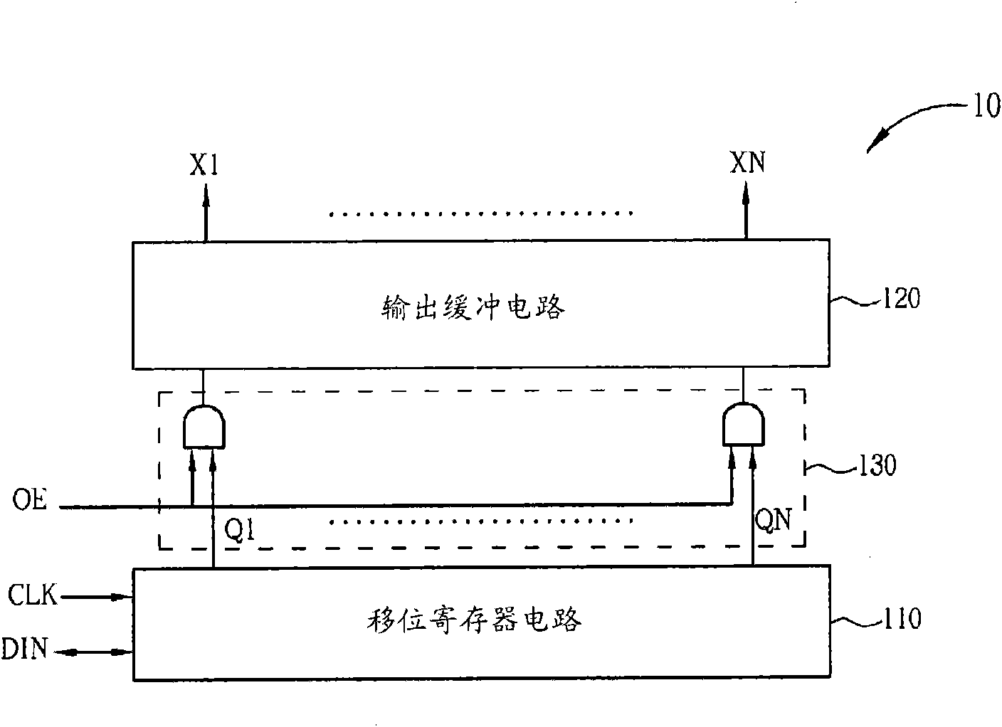
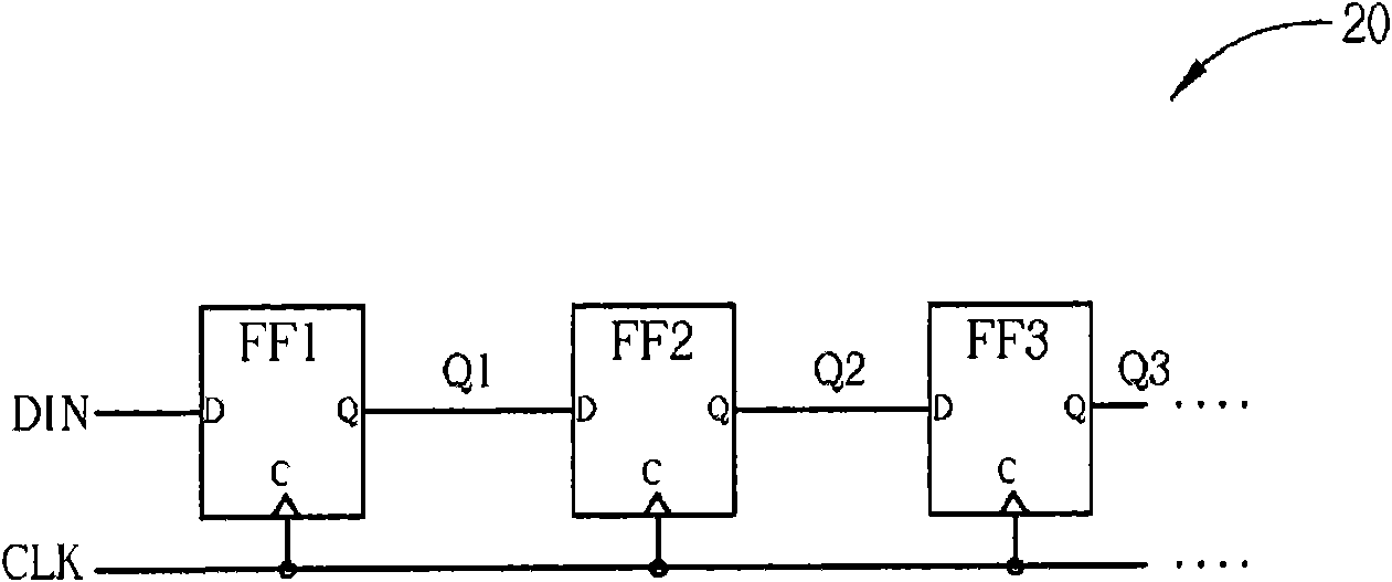
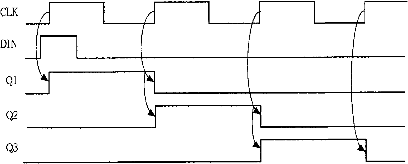
[0055] Please refer to Figure 6 , Figure 6 It is a schematic diagram of a driving device 60 for a liquid crystal display according to the present invention. The driving device 60 is used to avoid the erroneous operation of the shift register caused by the noise on the clock signal, and includes a receiving end 61 , a noise elimination circuit 62 , a control signal generating circuit 63 and a shift register 65 . The receiving end 61 is used for receiving a clock signal CLK. The noise elimination circuit 62 is coupled to the receiving end 61 for filtering the noise of the clock signal CLK and delaying the clock signal CLK for a preset time to generate a clock signal CLK2. The control signal generating circuit 63 is coupled to the receiving end 61 and the noise canceling circuit 62 for generating control signals SCK1 and SCK2 according to the clock signal CLK and the clock signal CLK2 to control the shift register 65 to output the driving signal of the LCD.

[0056] Therefor...


PUM


Abstract

The invention discloses a driving device for a liquid crystal display, which is used for avoiding operational errors of a shift register caused by noise on a clock signal. The driving device comprisesthe shift register, a receiving end, a noise canceling circuit and a control signal generation circuit, wherein the receiving end is used for receiving a first clock signal; the noise canceling circuit is coupled to the receiving end and used for canceling the noise of the first clock signal and delaying the first clock signal for a preset time so as to generate a second clock signal; and the control signal generation circuit is coupled to the receiving end and the noise canceling circuit and used for generating a first control signal and a second control signal according to the first and second clock signals so as to control the shift register.

Description

technical field [0001] The invention relates to a driving device for a liquid crystal display, in particular to a driving device for avoiding operation errors of the liquid crystal display caused by noise on a clock signal. Background technique [0002] In the driving circuit of liquid crystal display, the shift register (Shift Register) is a widely used digital logic circuit, which provides a pulse signal to multiple signal output terminals in sequence according to a clock signal, so that the driving circuit of liquid crystal display Data signals can be output row by row or gate signals can be output column by column to drive corresponding pixels. [0003] Please refer to figure 1 , figure 1 It is a functional block diagram of a gate driving circuit 10 of a known liquid crystal display. The gate driving circuit 10 mainly includes a shift register circuit 110 and an output buffer circuit 120 . The shift register 110 is used to sequentially generate pulse signals Q1 ˜ Qn ...

Claims


Application Information

Patent Timeline
Patent Type & Authority Applications(China)
IPC IPC(8): G09G3/36H03K5/24
Inventor 郑东栓刘岳修韩开旭
Owner NOVATEK MICROELECTRONICS CORP
Learn More