
Measuring fixture and measuring method of frozen soil dielectric constant

A technology of dielectric constant and measuring fixtures, which is applied in the direction of measuring electrical variables, measuring devices, and on-site foundation soil surveys. Manual operation to ensure the effect of comparability

Inactive Publication Date: 2011-04-27
BEIJING NORMAL UNIVERSITY
View PDF0 Cites 1 Cited by
  • Summary
  • Abstract
  • Description
  • Claims
  • Application Information

AI Technical Summary

Problems solved by technology

[0003] 1. Because the temperature of the frozen soil and the probe is different, the temperature state of the soil in the measured area will be changed after the two are in contact, and its temperature state has a great influence on the measurement result, so accurate measurement cannot be carried out;
[0004] 2. After the soil is frozen, it is very hard, and its outer surface cannot be in close contact with the probe, so it cannot be measured;
[0005] 3. The density of the soil to be measured cannot be known exactly, and the density of the soil to be measured is the most important parameter affecting the dielectric constant of the soil, which is crucial to the analysis of the measurement data;
[0006] 4. The measurement of the dielectric constant requires the sample to be tested to be uniform and isotropic, and the manual operation of the soil sample to be tested will inevitably destroy the uniform structure of the soil sample, resulting in measurement errors

Method used


Image

  • Measuring fixture and measuring method of frozen soil dielectric constant
  • Measuring fixture and measuring method of frozen soil dielectric constant
  • Measuring fixture and measuring method of frozen soil dielectric constant

Examples


Embodiment Construction

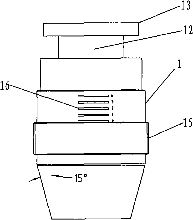
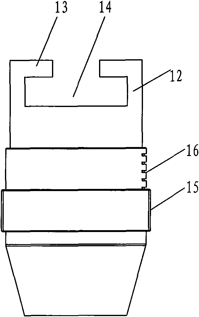
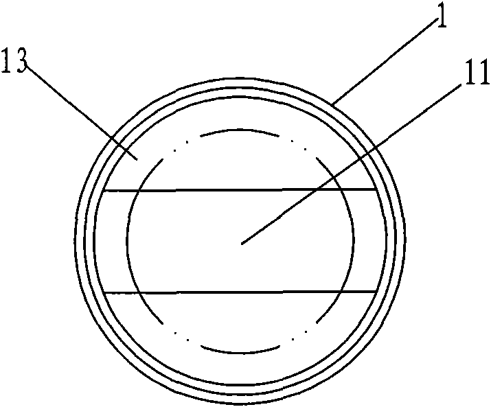
[0035] Such as figure 1 , figure 2 with image 3 As shown, the earth taker 1 is cylindrical, and it has a continuous cylindrical inner cavity 11. The upper end of the earth taker 1 is symmetrically provided with two side baffles 12 on the front, rear and both sides, and the top of each side baffle 12 is arranged. Semicircular baffle 13 is arranged, two baffles 13 are arranged symmetrically, there is a gap between the two baffles 13, the gap is greater than the diameter of the boom 52 of the probe 5, and the left and right sides of the soil fetcher 1 have openings 14. The earth taker 1, the side baffle 12 and the baffle 13 are integrally made. The middle part of the soil fetcher 1 is provided with an external thread 15, and the soil fetcher above the external thread 15 is provided with a measuring scale 16 along the vertical direction. The bottom of the soil extractor 1 is set as a circular frustum, and the diameter of the circular platform decreases gradually from top to ...


PUM


Abstract

The invention relates to a measuring fixture of a frozen soil dielectric constant, comprising a soil sampler, a soil roller and soil retaining components. The soil sampler is in a cylinder shape and provided with an internal cavity; both sides of the soil sampler are provided with openings; the middle part of the soil sampler is provided with external threads; measuring scales are arranged on thesoil sampler; the soil roller is in a cylinder shape and provided with an internal cavity; the middle part of the soil roller is provided with internal threads; the bottom of the soil roller is provided with a soil pressing block; the upper end surface of the soil roller is provided with scales; the soil roller is arranged outside the soil sampler rotatably; and the openings at both sides of the soil sampler are respectively provided with a soil retaining component. In the measuring fixture and the measuring method of the frozen soil dielectric constant, a probe is extended into a thermostated container to perform measurement, and soil samples and the probe are in close contact when the soil samples and the probe are not frozen, therefore, the measuring accuracy is high. Because both the soil sampler and the soil roller are provided with the scales, the volume weight of the measured soil samples can be accurately controlled, and the comparability of data measured for many times can beensured. Because the measuring fixture is adopted to perform measurement, the manual operation can be avoided, the conformity requirement of the measured soil samples on homogeneous isotropy can be ensured, and the measurement error can be reduced.

Description

technical field [0001] The invention relates to the measurement of the dielectric constant of frozen soil, in particular to a jig for measuring the dielectric constant of frozen soil and a measuring method. Background technique [0002] At present, a network analyzer is used to measure the dielectric constant of frozen soil. The conventional method is to place the sample under test under the probe of the network analyzer, and the probe 5 includes a disk 51 and a suspender 52 on the disk 51 (see Figure 9 with Figure 10 ), hold the sample to be tested or put the sample to be tested into a certain container, and squeeze it with the disc of the probe, so that the sample to be tested is in close contact with the disc, and then operate the network analyzer software for measurement. But this traditional measurement method is not suitable for measuring the dielectric constant of frozen soil. There are several reasons for this: [0003] 1. Because the temperature of the frozen s...

Claims


Application Information

Patent Timeline
Patent Type & Authority Patents(China)
IPC IPC(8): G01N1/08G01R27/26E02D1/04
Inventor 赵少杰张立新
Owner BEIJING NORMAL UNIVERSITY
Learn More