Lossless installation structure of floor and connecting piece used by same
A technology for installing structures and connectors, applied in building structures, floors, buildings, etc., can solve problems such as nail removal, floorboard damage, waste, etc., and achieve the effect of convenient disassembly and assembly and easy maintenance.
- Summary
- Abstract
- Description
- Claims
- Application Information
AI Technical Summary
Problems solved by technology
Method used
Image
Examples
Embodiment 1
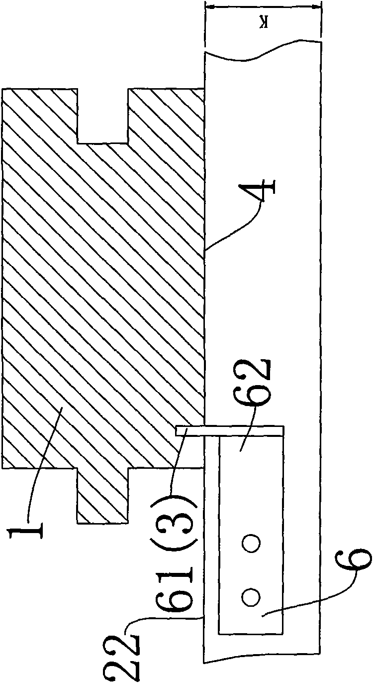
[0032] see figure 1 , 2 The floor non-destructive installation structure shown includes a keel fixed on the ground, the floor 1 is arranged on the keel 2 , and a positioning groove 3 is opened on the lower surface 4 of the floor. The positioning groove 3 extends longitudinally along the floor in the length direction. The depth direction of the positioning groove is perpendicular to the lower surface of the floor. Both sides of the floor 1 have a conventional notch structure.
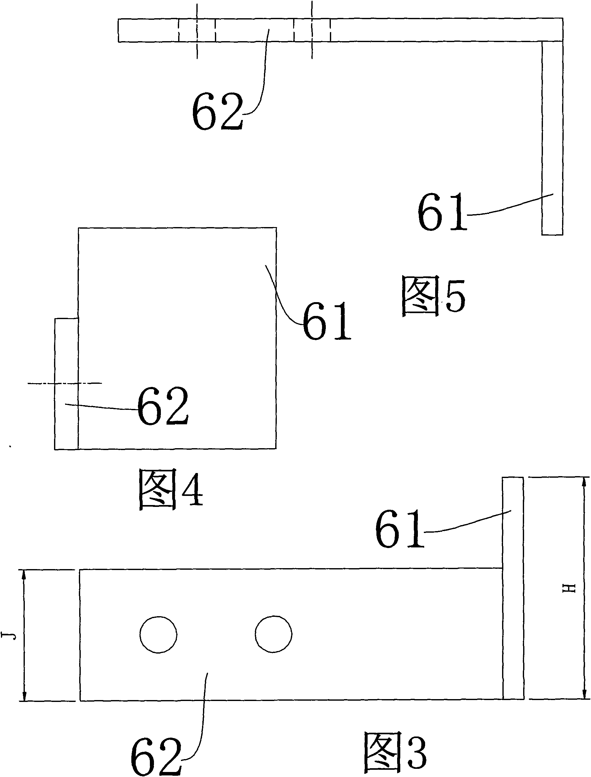
[0033] see Figure 3-5 As shown, the connector 6 has an integrated, vertically connected first connecting plate 61 and a second connecting plate 62 . The first connecting plate extends into the positioning groove, and the second connecting plate fits with the side of the keel. The second connecting plate extends from under the floor to the outside along the side 21 of the keel, and the second connecting plate extending below the floor is fixed on the side 21 of the keel by two nails 7 .
Embodiment 2
[0035] see Image 6 , 7 Embodiment 2 shown is different from Embodiment 1 in that: the angle between the depth direction of the positioning groove and the lower surface of the floor is 60°. see Figure 8-10 As shown, the connecting piece 6 has an integrated first connecting plate 61 , a second connecting plate 62 and a transition plate 63 . The side edge of the transition plate is connected to the second connecting plate; the top edge of the transition plate is connected to the first connecting plate. Both the transition plate and the first connecting plate are perpendicular to the second connecting plate. The angle between the first connecting plate 61 and the transition plate is 60°. The first connecting plate extends into the positioning groove, and the second connecting plate fits with the side of the keel. The second connecting plate extends from under the floor to the outside along the side 21 of the keel, and the second connecting plate extending below the floor is...
Embodiment 3
[0037] see Figure 11 , 12 16 shows embodiment 3, which is different from embodiment 2 in that: the positioning groove 3 is opened at the bottom of the floor side 5; the depth direction of the positioning groove is parallel to the lower surface 4 of the floor. see Figure 13-15 In the connecting piece 6 shown, the first connecting plate 61 is perpendicular to the direction of the transition plate. The first connecting plate 61 extends into the positioning groove 3 .
[0038] In embodiments 1 and 2, the height H of the connecting piece is lower than the height K of the keel; in embodiment 3, the height H of the connecting piece may be higher than the height K of the keel. However, in each embodiment, the height J of the second connecting plate 62 should be lower than the height K of the keel, so as to prevent the second connecting plate 62 protruding from the upper surface 22 of the keel and obstructing the installation of the floor.
PUM
 Abstract
Description
Claims
Application Information
 - R&D Engineer
- R&D Manager
- IP Professional
- Industry Leading Data Capabilities
- Powerful AI technology
- Patent DNA Extraction
Browse by: Latest US Patents, China's latest patents, Technical Efficacy Thesaurus, Application Domain, Technology Topic, Popular Technical Reports.
© 2024 PatSnap. All rights reserved.Legal|Privacy policy|Modern Slavery Act Transparency Statement|Sitemap|About US| Contact US: help@patsnap.com


