Labor-saving heavy duty punch

A punching machine, a heavy-duty technology, applied in the field of punching machines, can solve the problems of increased usage restrictions, inability to change the distance, unable to achieve labor-saving pressing, etc., to achieve the effect of reducing force, not easy to damage, and easy to install

Inactive Publication Date: 2010-03-10
APEX MFG
View PDF0 Cites 2 Cited by
  • Summary
  • Abstract
  • Description
  • Claims
  • Application Information

AI Technical Summary

Problems solved by technology

[0003] However, the existing punching machine is only for double-hole punching. This kind of double-hole punching machine is limited by its appearance, so that it cannot get enough force arm, and cannot achieve the effect of labor-saving pressing. Not only that , the distance between the two punching positions cannot be changed, which increases the restrictions on use, and can only punch holes for a small amount of paper in use. For the above problems, it is urgent to improve

Method used


Image

  • Labor-saving heavy duty punch
  • Labor-saving heavy duty punch
  • Labor-saving heavy duty punch

Examples


Embodiment Construction

[0033] Regarding the technology, means and effects used in the present invention, a preferred embodiment is given and described in detail below with drawings, which are for illustration purposes only, and are not limited by this structure in the patent application.

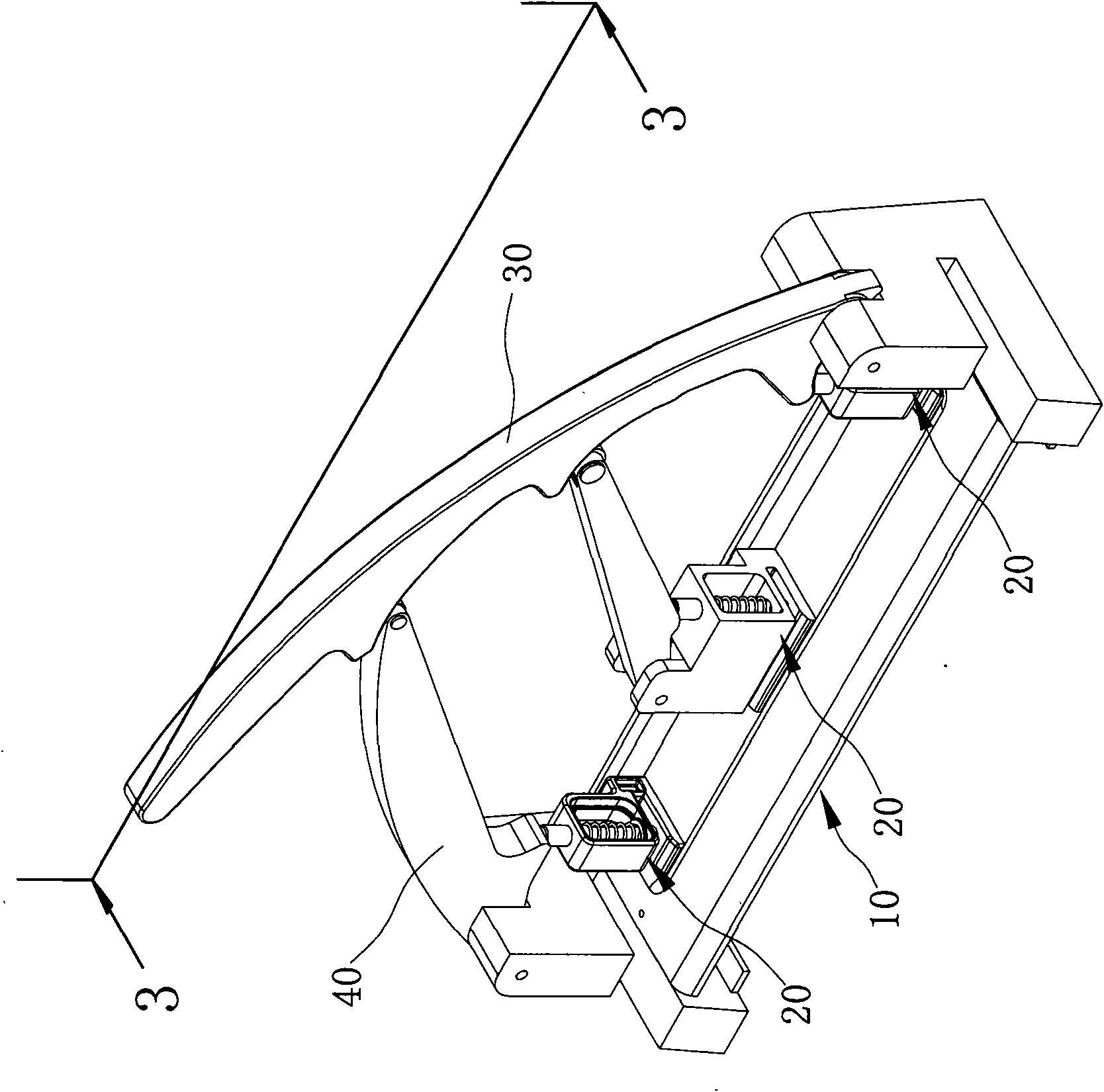
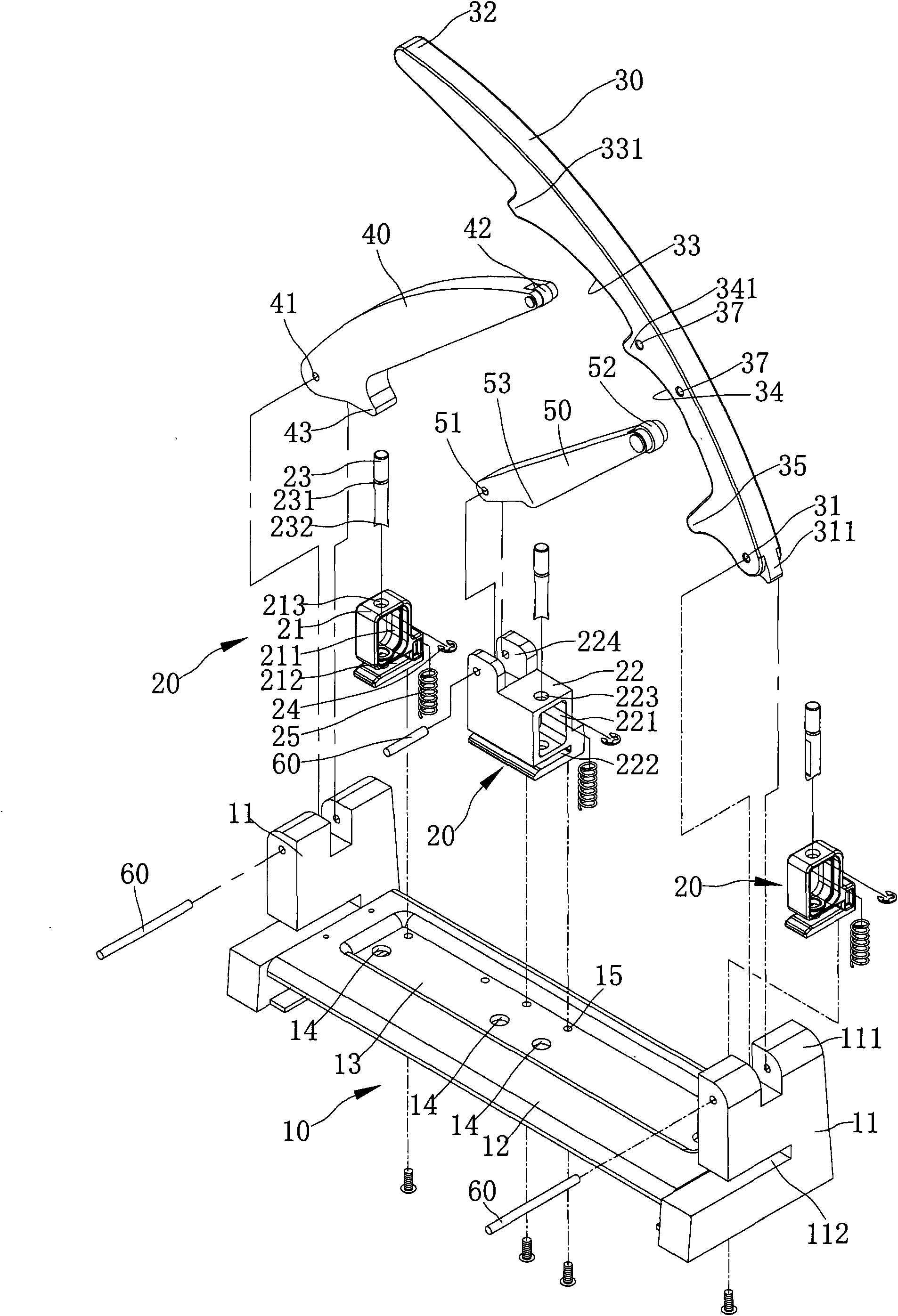
[0034] refer to figure 1 as well as figure 2 , is a three-dimensional appearance view and a three-dimensional exploded view of the present invention. The present invention includes a base 10, three punching devices 20, a control member 30, a first pressing member 40 and a second pressing member 50, and the punching device 20 It is installed on the base 10 according to the requirements, and the control part 30 is pivotally connected with the base 10, and one end of the two pressing parts 40, 50 is respectively connected with the base 10 and the punching device 20, and the other end is slidable against the control part 30. On the inner side, the control member 30 presses against the first pressing member 40 for pu...


PUM


Abstract

The invention provides a labor-saving heavy duty punch, which comprises a base, a control piece, a first pressing piece, and two punching devices, wherein two ends of the base are respectively provided with a pivot part, and a working table is arranged between two pivot parts; the control piece is pivoted at one end of the base; the other end of the control piece opposite to the base is provided with a control part for a user to press; the control piece is provided with a first chute relative to the base, and is provided with a pressing part adjacent to the base; the first pressing piece is pivoted at one end of the shell opposite to the control piece; one end of the first pressing piece opposite to the base is arranged in the first chute in a sliding way; the first pressing piece and thecontrol piece generate pivotal swing toward opposite directions; a position where the first pressing piece is supported against the first chute is provided with a first sliding pivot for changing a force application arm; the first pressing piece is provided with a pressing part adjacent to the base; and the two punching devices are arranged on the working table, and are respectively pressed by thecontrol piece and the pressing part of the first pressing piece for punching.

Description

technical field [0001] The invention relates to a punching machine, especially a punching machine with good labor-saving effect. Background technique [0002] For example, the "Puncher" patent case of the People's Republic of China Patent Grant No. CN2706293Y is characterized in that: the puncher also includes a cover covering the pressing arm, and the locking mechanism includes a positioning The pivot block, the front end of the positioning pivot block forms a toggle piece, the middle section is provided with a through hole, and the rear end forms a stop surface with a through hole, and the other end of the stop surface forms a A clamping block with a U-shaped opening, a positioning clamping groove is provided between the stop surface and the clamping block, and a shaft sleeve protruding from the outer edge of the block is embedded and positioned between the clamping groove and the clamping block; in addition , the actuating groove is a slot mouth with a narrow top and a w...

Claims


Application Information

Patent Timeline
Patent Type & Authority Applications(China)
IPC IPC(8): B26F1/02B26D5/10
Inventor 蔡富丞
Owner APEX MFG
Why Eureka
Try Eureka