
Realization method of zero-current switch of diode neutral point clamped inverting circuit

A technology of inverter circuit and implementation method, which is applied in the direction of high-efficiency power electronic conversion, conversion of AC power input to DC power output, electrical components, etc., and can solve problems such as complex PWM signal relationship, complicated commutation process, and increased commutation loss , to achieve the effect of reducing circuit cost, simple logic relationship, and reducing switching loss

Inactive Publication Date: 2012-11-21
EAST CHINA JIAOTONG UNIVERSITY
View PDF3 Cites 0 Cited by
  • Summary
  • Abstract
  • Description
  • Claims
  • Application Information

AI Technical Summary

Problems solved by technology

[0005] Although the above-mentioned schemes can realize the soft switching operation of the main power tube, there are still the following disadvantages after careful analysis: (1) all need to add four auxiliary power tubes and four auxiliary freewheeling diodes; (2) the auxiliary power tube The relationship between the PWM signal and the PWM signal of the main power tube is complicated, and it is not easy to generate; (3) The commutation process is complicated, and there are many branches flowing through it, which also increases additional commutation loss

Method used


Image

  • Realization method of zero-current switch of diode neutral point clamped inverting circuit
  • Realization method of zero-current switch of diode neutral point clamped inverting circuit
  • Realization method of zero-current switch of diode neutral point clamped inverting circuit

Examples


Embodiment Construction

[0037]Attached below Figure 8 , its parallel three-port unit M1 and parallel three-port unit M2 each contain two basic units, further illustrating the characteristics and principles of the present invention.

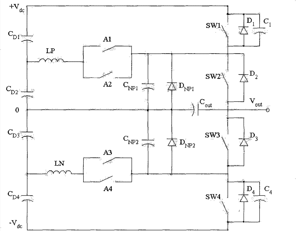
[0038] The method of zero-current switching of the diode mid-point clamp inverter circuit of the present invention is such that the circuit consists of a series connected DC power supply u s1 and u s2 The input power composed of six main power tubes (Q 1 -Q 6 ), ten freewheeling diodes (D 1 ~D 10 ) consists of an inverter bridge arm, consisting of four commutation inductors (L 1 ~ L 4 ) commutation link, the filter inductor L f and filter capacitor C f Composed of AC filter circuit, load R composition. Among them, the power tube Q 1 and its anti-parallel diode D 1 , commutation inductance L 1 and freewheeling diode D 7 Constitutes the basic unit 1 of the parallel three-port unit M1; where the power tube Q 2 and its anti-parallel diode D 2 , commutation in...


PUM


Abstract

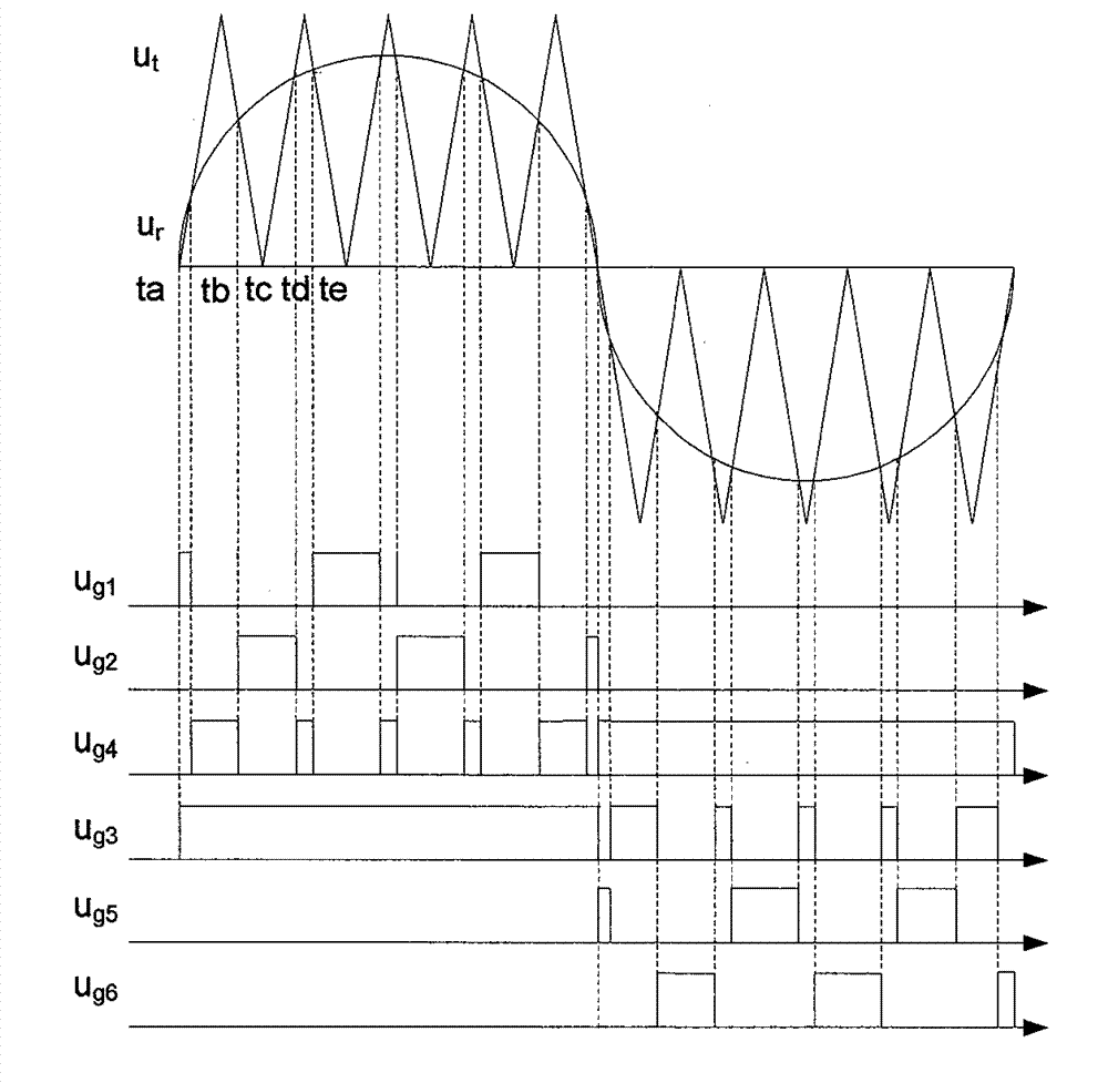
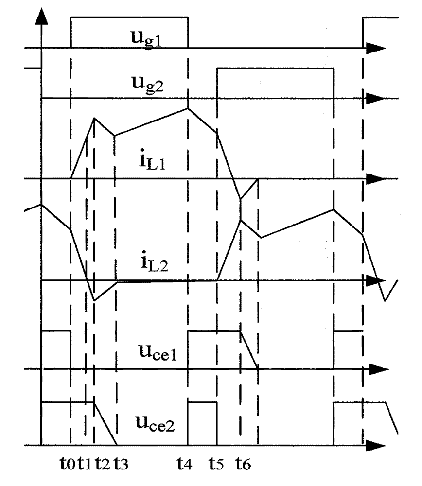
The invention relates to a zero-current switching realization method of a zero-current switch of a diode neutral point clamped inverting circuit, which is realized by the diode neutral point clamped inverting circuit; parallel-connection three-port units M1 and M2 which form the circuit are respectively composed of basic units of N parallel-connection three-port units M1 or M2, which are connected in parallel, the basic unit of the parallel-connection three-port unit M1 (M2) is composed of a power tube Q1 (Q5) and anti-parallel diode D1 (D5) thereof, and a freewheel diode D7 (D9) and a conversion current inductance L1 (L3). All power tubes of 1-N basic units of M1 and M2 are triggered in a circulating way according to the sequence of from 1 to N, and the trigger pulse duty ratio of each power tube is less than 1 / N; the trigger logic of a main power tube Q4 (Q3) is determined by an output logic signal which is obtained by that one N-path input nor gate is input by the trigger logic of N power tubes of N basic units of M1 (M2). The method can realize zero-current switching on of all the power tubes in the basic units.

Description

technical field [0001] The invention relates to a method for realizing zero-current turn-on in a zero-current switch of a diode mid-point clamp inverter circuit, and belongs to the technical field of high-frequency inverter circuits. Background technique [0002] Compared with the traditional half-bridge inverter circuit, the diode mid-point clamp inverter circuit can reduce the rated voltage level of the power tube, reduce the loss of the power tube, and reduce the ripple current of the filter inductor, thereby reducing the distortion of the output voltage. Therefore, although the diode mid-point clamp inverter circuit uses more power semiconductor devices, it still has more advantages in the application of medium and high-power inverter power applications. [0003] In order to further reduce the power tube switching loss of the neutral-point clamped inverter circuit, some soft-switching neutral-point clamped inverter circuits have also been proposed. The typical scheme is ...

Claims


Application Information

Patent Timeline
Patent Type & Authority Patents(China)
IPC IPC(8): H02M7/797
CPCY02B70/1491Y02B70/10
Inventor 袁义生
Owner EAST CHINA JIAOTONG UNIVERSITY
Learn More