
Pressure sensor method and apparatus

A pressure sensor and pressure technology, applied in the direction of measuring fluid pressure, measuring fluid pressure through electromagnetic components, instruments, etc., can solve the problem of not considering the strong combination of the sensing die and the support

Inactive Publication Date: 2010-02-24
HONEYWELL INT INC
View PDF0 Cites 7 Cited by
  • Summary
  • Abstract
  • Description
  • Claims
  • Application Information

AI Technical Summary

Problems solved by technology

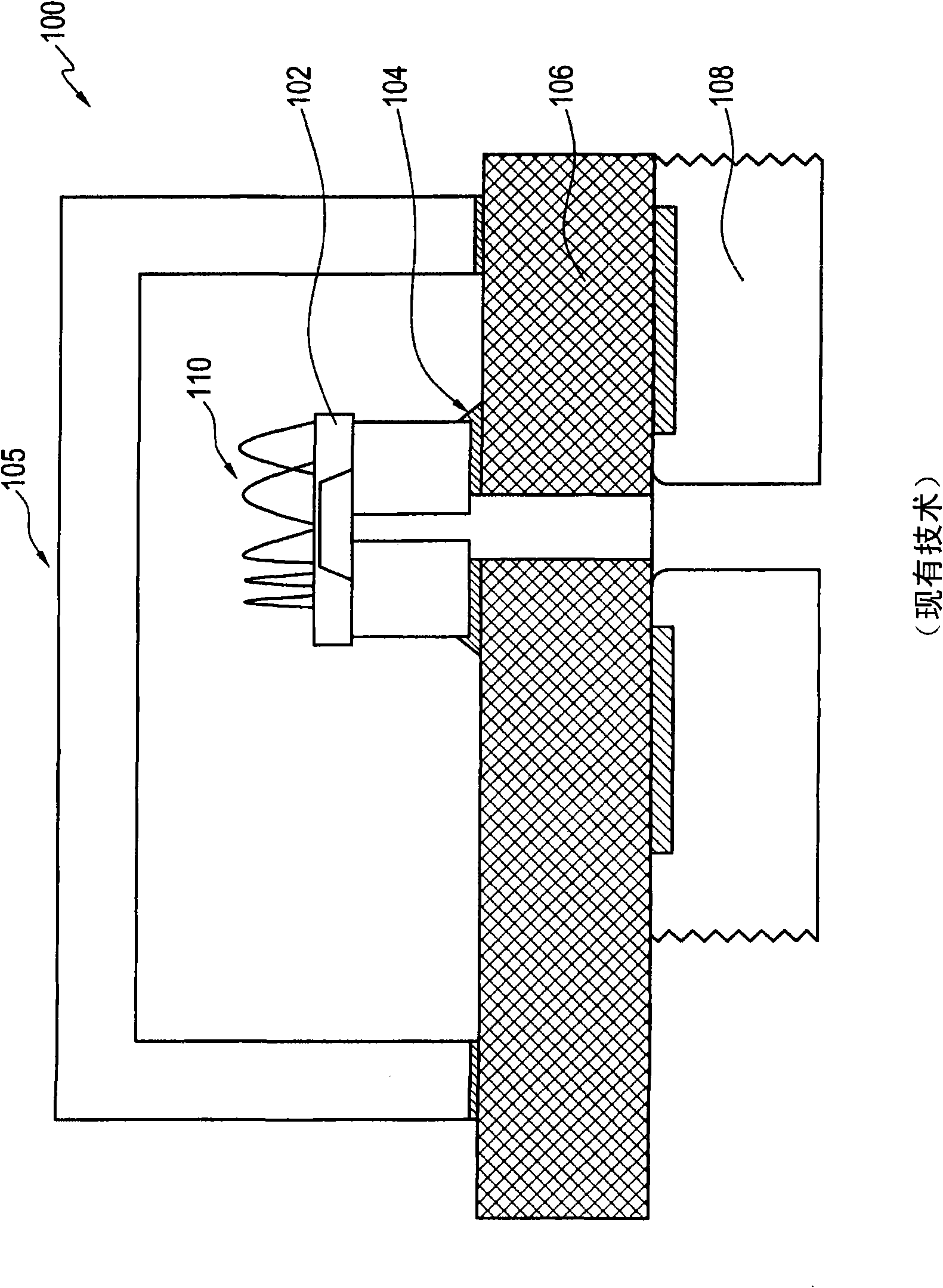
[0010] figure 1 A problem with the prior art configuration shown in -4 is that such a design requires reliable operation in the aforementioned conditions and the use of attachment materials of high strength and chemical resistance
Removing this material from the plating process does not account for the strong bond between the sensing stamp and the standoff

Method used


Image

  • Pressure sensor method and apparatus
  • Pressure sensor method and apparatus
  • Pressure sensor method and apparatus

Examples


Embodiment Construction

[0023] The specific values ​​and configurations discussed in these non-limiting examples may vary and are cited merely for illustration of at least one embodiment and are not intended to limit the scope of the invention.

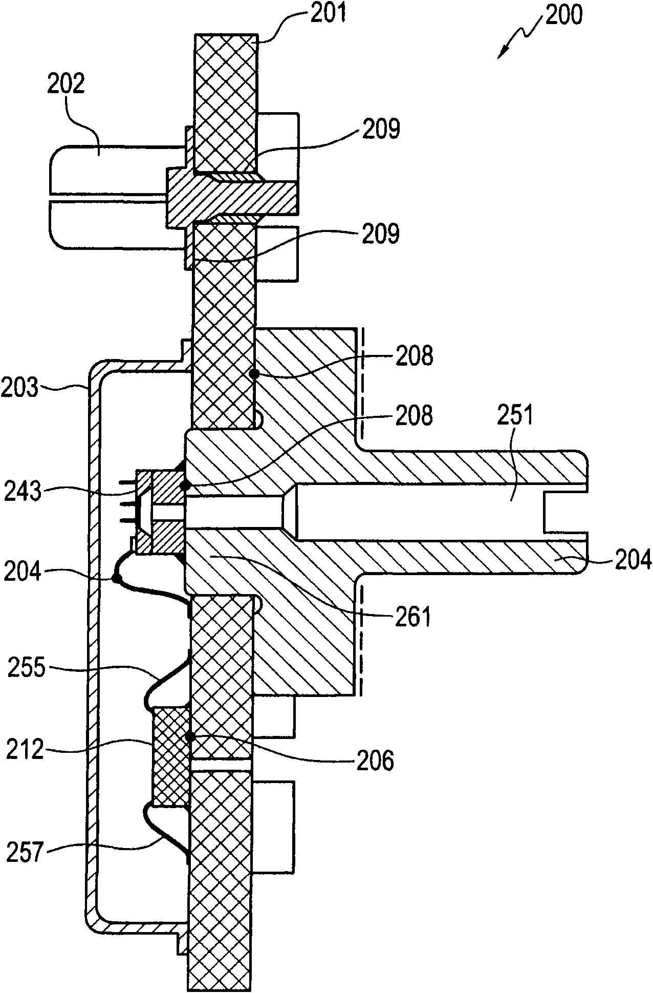
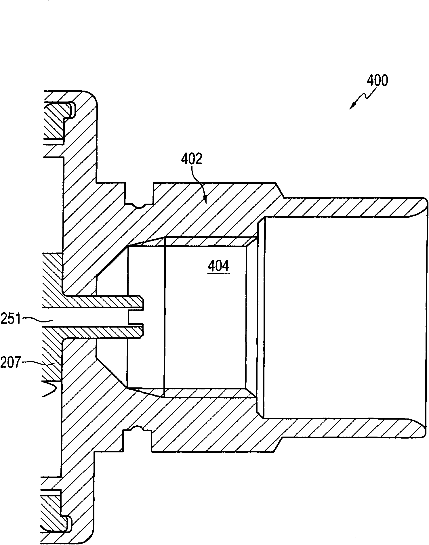
[0024] See the accompanying drawings below, and in particular Figure 5 , which shows a view of the bonding side of a pressure sensor device 500 that can be implemented according to a preferred embodiment. in addition, Figure 6 shows that according to a preferred embodiment Figure 5 A side cross-sectional view of pressure sensor device 500 is shown. noticed in Figure 5 and Figure 6 The same reference numerals are used to denote the same or similar parts or elements. in addition, Figure 5 and Figure 6 Components that are also shown in the prior art views of FIGS. 2-4 are shown. However be aware that: Figure 5 and Figure 6 These components are shown to demonstrate improvements and differences between pressure sensor device 500 and prior art d...


PUM


Abstract

A pressure sensor apparatus and a method of forming the same. A substrate (201 (e.g., Printed circuit board, PCB) can be provided that includes a top side and a bottom side. A pressure transducer (243) can be directly bonded to the top side of the substrate (201), wherein the substrate comprises substrate walls forming a plated through-hole (553) that allows for the passage of a sensed media to contact a back side of the pressure transducer (243). Thereafter, a metal carrier (504) with an integral port (551) is bonded to the bottom side of the substrate (201), thereby forming a chip-on-board pressure sensor (500) in which the need for a plating or coating to allow adhesion between the pressure transducer (243) and the metal carrier (504) is eliminated. The pressure transducer may comprise,for example, silicon or silicon bonded to glass. The metal carrier can be provided with a feature that mates with a valve such as a Schrader valve.

Description

[0001] Cross references to related patent applications [0002] This patent application claims priority to US Provisional Patent Application No. 60 / 911,554, filed April 13, 2007, which is hereby incorporated by reference in its entirety. technical field [0003] Embodiments of the invention generally relate to pressure sensors and pressure transducers. Embodiments of the invention also relate to components and configurations employing chip-on-board packaging. Embodiments of the present invention further relate to pressure sensor assemblies employing a chip-on-board packaging process. Background technique [0004] Various processes and devices have been used in the field of pressure sensing. Pressure sensors are commonly used and deployed where monitoring and responding to pressure changes is required. Pressure sensors are commonly used in a variety of applications including automotive, aerospace, commercial, industrial, and consumer. [0005] An operating environment is ...

Claims


Application Information

Patent Timeline
Patent Type & Authority Applications(China)
IPC IPC(8): G01L9/00
Inventor W·A·兰布L·F·里克斯A·D·布拉德利
Owner HONEYWELL INT INC
Learn More