Intelligent binder
A binding device and intelligent technology, applied in the direction of freight vehicles, load fixing, motor vehicles, etc., can solve the problems of complex overall structure, increase difficulty, slow binding speed, etc., achieve simple device structure, improve safety, The effect of eliminating security risks
- Summary
- Abstract
- Description
- Claims
- Application Information
AI Technical Summary
Problems solved by technology
Method used
Image
Examples
Embodiment 1
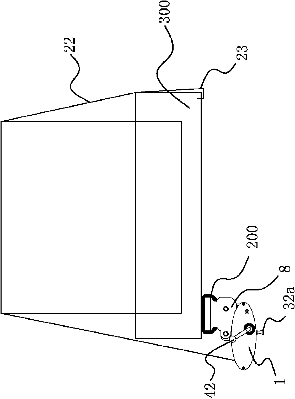
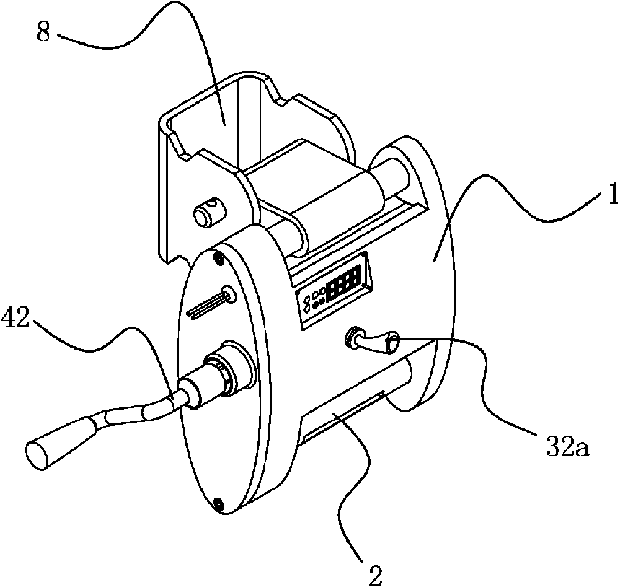
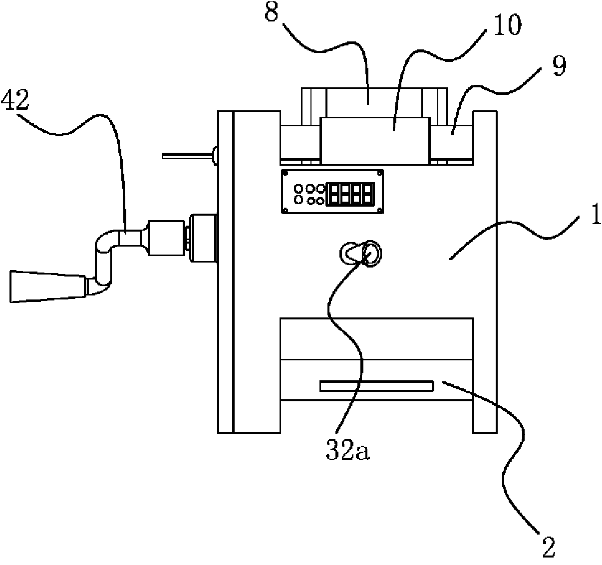
[0033] Such as figure 1 As shown, the body 1 of the smart binder is installed on the car body 300 through the rail 200 . More specifically, as Image 6 As shown, the main body 1 is provided with a horizontal shaft 9, a connecting sleeve 10 is set on the horizontal shaft 9, and a beam 81 is provided on the bracket 8. Make the connection. The binder includes a body 1 , a self-locking mechanism 3 arranged on the body 1 , a power mechanism, and a reel 2 rotatably connected to the body 1 . In this embodiment, the power mechanism is an electric power mechanism 5 . The self-locking mechanism 3 is connected with the spool 2 and can drive the spool 2 to rotate under the drive of the power mechanism, and the self-locking mechanism 3 can prevent the spool 2 from rotating in reverse when the power mechanism stops working. A binding belt 22 is connected to the reel 2 , and a belt hook 23 is fixed at the outer end of the binding belt 22 .
[0034] As shown in FIG. 28 , the electric pow...
Embodiment 2
[0039] Such as Image 6 As shown, in this embodiment, the power mechanism includes a manual power mechanism 4 and an electric power mechanism 5 . The manual power mechanism 4 is coupled to the reduction end of the multi-stage reduction planetary gear set. The manual power mechanism 4 includes a manual gear 41 and a handle 42 coupled to the manual gear 41 through a detachable structure and capable of driving the manual gear 41 to rotate. The hand gear 41 has a non-circular connecting portion 41a, the handle 42 has a connecting hole 42a matching the shape of the connecting portion 41a, and the connecting portion 41a is inserted into the connecting hole 42a. The non-circular shape of the connecting portion 41a facilitates the better positioning of the handle 42 when it cooperates with it, and also provides a better focus point for the entire operation. The manual gear 41 meshes with the aforementioned output gear 31c.
[0040] As shown in Fig. 28, a clutch mechanism 6 is provi...
PUM
 Abstract
Description
Claims
Application Information
 - Generate Ideas
- Intellectual Property
- Life Sciences
- Materials
- Tech Scout
- Unparalleled Data Quality
- Higher Quality Content
- 60% Fewer Hallucinations
Browse by: Latest US Patents, China's latest patents, Technical Efficacy Thesaurus, Application Domain, Technology Topic, Popular Technical Reports.
© 2025 PatSnap. All rights reserved.Legal|Privacy policy|Modern Slavery Act Transparency Statement|Sitemap|About US| Contact US: help@patsnap.com


