Signal processing device
A signal processing device and signal technology, applied in transducer circuits, speech analysis, instruments, etc., to achieve the effect of simplifying the hardware structure, reducing the manufacturing cost, and simplifying the circuit structure
- Summary
- Abstract
- Description
- Claims
- Application Information
AI Technical Summary
Problems solved by technology
Method used
Image
Examples
Embodiment 1
[0048] (1.1. Structure of signal processing device)
[0049] figure 1 It is a block diagram showing an example of the configuration of the signal processing device 1 of the first embodiment. Here, the signal processing device 1 is a signal processing device that restores a source signal output from a target sound source 10 among a plurality of sound sources (fluctuation sources) 10 (10a, 10b) to a target signal. In the signal processing device 1 , as a separation method, a closed sound source separation method based on a so-called independent component analysis method is adopted.
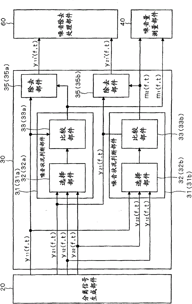
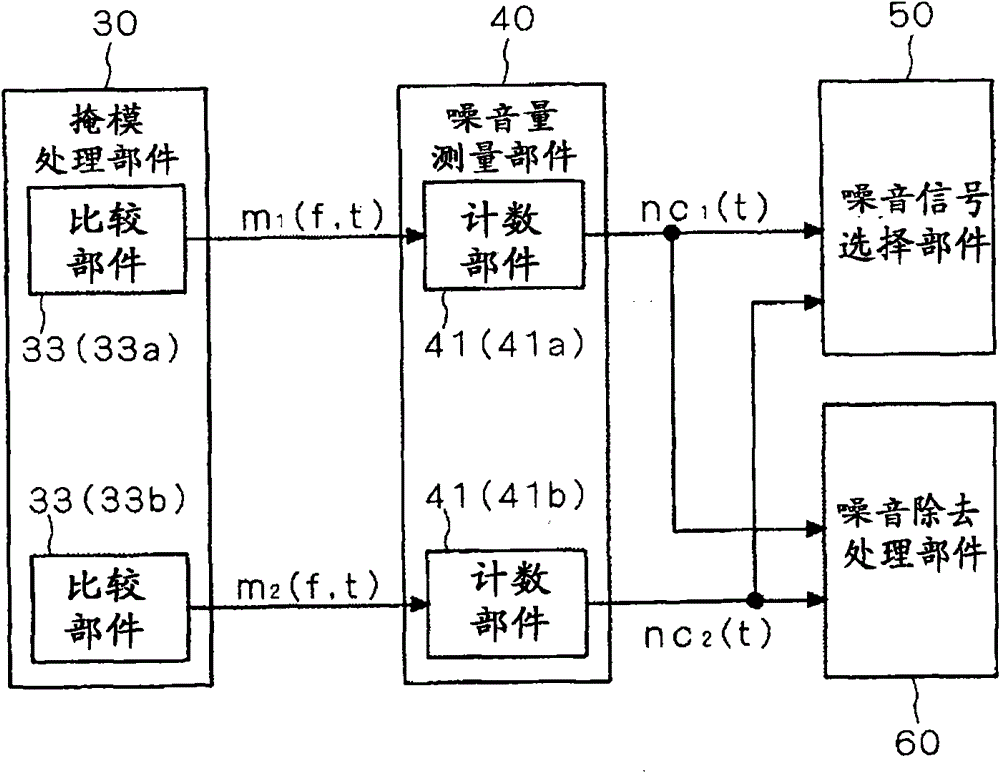
[0050] Such as figure 1 As shown, the signal processing device 1 mainly includes an observation unit 15 , a separated signal generation unit 20 , a mask processing unit 30 , a noise amount measurement unit 40 , a noise signal selection unit 50 , and a noise removal processing unit 60 .
[0051] Each of the plurality of microphones 15 (15a, 15b) is an observation means for observing a mixed signal...
Embodiment 2
[0115] Next, Embodiment 2 of the present invention will be described. The signal processing device 100 of the second embodiment is the same as that of the first embodiment except that the configuration of the noise amount measuring unit 140 is different from that of the first embodiment. Therefore, the following description will focus on this difference. In addition, in the following description, the same reference numerals are assigned to the same constituent elements as those in the first signal processing device 1 . Since these structural elements with the same reference numerals have already been described in Embodiment 1, description thereof will be omitted in this embodiment.
[0116] (2.1. Structure of signal processing device)
[0117] Figure 10 It is a block diagram showing an example of the overall configuration of the signal processing devices 100 and 200 in the second and third embodiments. Figure 11 It is a block diagram showing an example of the structure o...
Embodiment 3
[0130] Next, Embodiment 3 of the present invention will be described. The signal processing device 200 of the third embodiment is the same as that of the first embodiment except that the configuration of the noise amount measuring means 240 is different from that of the first embodiment. Therefore, the following description will focus on this difference. In addition, in the following description, the same reference numerals are assigned to the same constituent elements as those in the first signal processing device 1 . Since these structural elements with the same reference numerals have already been described in Embodiment 1, their description is omitted in this embodiment.
[0131] (3.1. Structure of signal processing device)
[0132] Figure 12It is a block diagram showing an example of the structure of the noise amount measuring means 240 of the third embodiment. Figure 13 and Figure 14 is a diagram for explaining the state of expansion of the second split signal. ...
PUM
 Abstract
Description
Claims
Application Information
 - R&D Engineer
- R&D Manager
- IP Professional
- Industry Leading Data Capabilities
- Powerful AI technology
- Patent DNA Extraction
Browse by: Latest US Patents, China's latest patents, Technical Efficacy Thesaurus, Application Domain, Technology Topic, Popular Technical Reports.
© 2024 PatSnap. All rights reserved.Legal|Privacy policy|Modern Slavery Act Transparency Statement|Sitemap|About US| Contact US: help@patsnap.com


