
A signaling collection device and method

A collection device and signaling technology, applied in the field of communication, can solve problems such as difficult cost reduction, difficulty in ensuring accuracy, increase in implementation difficulty and failure points, and achieve the effect of satisfying automation and intelligence

Inactive Publication Date: 2011-12-07
ZTE CORP
View PDF0 Cites 0 Cited by
  • Summary
  • Abstract
  • Description
  • Claims
  • Application Information

AI Technical Summary

Problems solved by technology

[0005] Generally speaking, the traditional technology is realized by using time slot crossover convergence equipment and E1 acquisition equipment together. After many input E1s are converged by time slot crossover equipment, the signaling time slots are converged to a small number of output E1 ports, and then sent to The E1 collection equipment is used for collection. Here, it is necessary to manually configure the exchange configuration table to exchange and configure the signaling time slots, which increases the difficulty of the project and makes it difficult to ensure the accuracy. Moreover, since two devices are required to cooperate to realize the collection of signaling, it is not easy to reduce Cost; there is a problem of cooperation between multiple devices, which introduces more fault points; even if the time slot scanning is implemented in the time slot convergence device, the scanning result must be sent to the other party, and there is a problem of interaction between the two, which increases the difficulty of implementation and point of failure

Method used


Image

  • A signaling collection device and method
  • A signaling collection device and method
  • A signaling collection device and method

Examples


Embodiment Construction

[0035] The technical solutions of the present invention will be described in more detail below with reference to the accompanying drawings and embodiments.

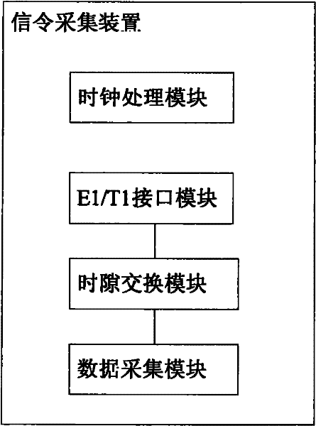
[0036] figure 1 is a schematic diagram of a signaling collection device according to an embodiment of the present invention, such as figure 1 As shown, the signaling collection device in this embodiment includes an E1 / T1 interface module, a time slot exchange module, a data collection module and a clock processing module.

[0037] The E1 / T1 interface module includes an E1 / T1 interface chip and an additional E1 / T1 interface protection circuit. It is mainly used to complete the code type conversion of the E1 / T1 signal link. The E1 / T1 interface chip realizes that the input encoding format is HDB3 (High Density Bipolar 3, third-order high-density bipolar code) or AMI (AlternateMark Inversion, bipolar alternate inversion code) converted into NRZ (No Return Zero, non-return to zero code) highway signal (highway signal is a ser...


PUM


Abstract

The present invention relates to a signaling collection device and method. The signaling collection device includes: an E1 / T1 interface module, which is used to realize E1 / T1 signal link code conversion to obtain a first serial signal, and convert the first serial signal to Send to the time slot exchange module; the time slot exchange module is used to copy the first serial signal to the data acquisition module, and identify the signaling time slot in the first serial signal received by the data acquisition module Perform exchange configuration to obtain the second serial signal, and send the second serial signal to the data acquisition module; the data acquisition module is used to identify the signaling time in the first serial signal copied by the time slot exchange module The slot is returned to the time slot exchange module, and data acquisition is performed on the second serial signal after the time slot exchange module exchanges and configures. According to the invention, the signaling time slot can be automatically identified, and the signaling time slot can be automatically configured and the data collection of the signaling time slot can be automatically configured according to the identification result, so as to meet the requirements of automation and intelligentization of signaling collection.

Description

technical field [0001] The present invention relates to the field of communications, in particular to a signaling acquisition device and method capable of automatically identifying signaling time slots. Background technique [0002] E1 / T1 is an interface widely used in the communication field. E1 is a European standard with a rate of 2.048Mbps; T1 is a North American standard with a rate of 1.544Mbps. Here only E1 is used as an example to illustrate. From the point of view of the physical interface, the E1 interface uses time division multiplexing to transmit data. Specifically, a frame is divided into 32 time slots, and each time slot is 8 bits (bits). TS0 is a synchronization time slot, TS1-TS31 are signaling or voice time slots; from the perspective of the transmission channel, if a time slot is used as a channel, the transmission rate is 64Kbps; if several time slots are combined as a channel, the transmission rate is The rate is Nx64Kbps; if a time slot is divided into...

Claims


Application Information

Patent Timeline
Patent Type & Authority Patents(China)
IPC IPC(8): H04Q3/00H04J3/12
Inventor 袁玉厂周建国汪承研胡芳华
Owner ZTE CORP
Learn More