Motor and electronic apparatus having the same

A motor and rotor technology, which is applied in the field of motors, can solve the problems of reduced accuracy of speed detection and reading, and achieve the effect of reducing the number of assembly processes and reducing costs

Inactive Publication Date: 2010-02-10
PANASONIC CORP
View PDF3 Cites 2 Cited by
  • Summary
  • Abstract
  • Description
  • Claims
  • Application Information

AI Technical Summary

Problems solved by technology

As a result, in this structure, there is a problem that the FG pattern is easily affected by the magnetic gas generated by the main magnetization and the iron core, and the reading accuracy of the speed detection is lowered.

Method used


Image

  • Motor and electronic apparatus having the same
  • Motor and electronic apparatus having the same
  • Motor and electronic apparatus having the same

Examples


Embodiment approach 1

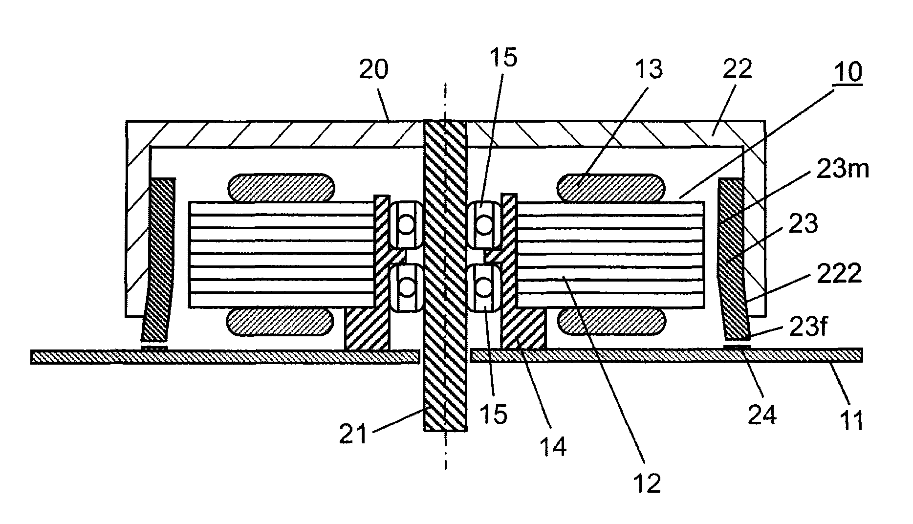
[0026] figure 1 It is a sectional view of the motor in Embodiment 1 of the present invention. First, refer to figure 1 The overall structure of this motor will be described.

[0027] Such as figure 1 As shown, the motor of this embodiment is an outer rotor type brushless DC motor as an example, and includes a stator 10 and a rotor 20 facing the stator 10 and rotatably arranged on the outer peripheral side.

[0028] The stator 10 has a stator core 12 mounted on a wiring board 11 . This stator core 12 is formed as a laminated body in which a plurality of plate-shaped bodies are laminated. On the outer peripheral portion of the stator core 12 , a plurality of teeth serving as magnetic poles are arranged at predetermined intervals along the circumferential direction. In addition, a coil 13 is wound around an arm portion constituting an inner magnetic circuit of each tooth. In this way, the stator 10 in which the coil 13 is wound around the stator core 12 is configured. In a...

Embodiment approach 2

[0061] Figure 5 It is a schematic explanatory diagram of an electronic device (for example, a laser printer) according to Embodiment 2 of the present invention. exist Figure 5 In this example, the motor 30 described in Embodiment 1 is mounted on the wiring board 11 . Furthermore, on this wiring board 11, in addition to the FG pattern 24 ( figure 1 shown), electronic components (not shown) and the like required for the entire electronic device are also loaded together.

[0062] The lower end of the rotating shaft 21 of the rotor 30 passes through the through hole ( figure 1(shown) extends to the lower portion of the wiring board 11, and a gear case 51 is connected to the lower portion of the rotating shaft 21. As described in detail in the first embodiment, the FG pattern 24 is arranged on the wiring board 11 to detect the speed of the motor 30 . The rotation of the motor 30 is decelerated by the gear box 51 . The rotational driving force of the motor 30 is further tran...


PUM


Abstract

The motor of the invention is an outer rotor type motor, and a rotor includes a cylindrical rotor frame that is opened at one end thereof in an axial direction, and a hollow cylindrical magnet attached to an inner periphery of the rotor frame. The magnet has a joining portion joined to an inside cylindrical portion of the rotor frame, and a protruding portion that further protrudes in the axial direction from one end, the outer diameter of the protruding portion is larger than the inner diameter of the rotor frame, and the joining portion is directly brought into close contact with a portion ranging from the one end to at least a portion of the inside cylindrical portion.

Description

technical field [0001] The present invention relates to an outer rotor type electric motor, and more particularly to an electric motor having a rotor in which magnets are directly attached to a rotor frame, and an electronic device having the electric motor. Background technique [0002] In recent years, the miniaturization of electronic equipment has progressed, and motors mounted in electronic equipment such as copiers and printers have also been required to be miniaturized. In addition, as such a motor, a brushless DC motor capable of easy rotation control is generally mounted on the above-mentioned equipment. [0003] As means for detecting the rotation speed for rotation control, a speed detection device utilizing a power generation function called a frequency generator or simply FG is widely used. Since the frequency generator generates a power generation signal (hereinafter referred to as FG signal) for speed detection, a magnetic pattern for power generation (herein...

Claims


Application Information

Patent Timeline
Patent Type & Authority Applications(China)
IPC IPC(8): H02K1/27H02K1/28H02K15/03H02K29/00
CPCH02K29/12H02K21/22
Inventor 小林正彦米井康夫中丸彻安田宪人浅井弘纪浅井裕之和田幸治
Owner PANASONIC CORP
Why Eureka
Try Eureka