Assembly method for forming a seating structure of a vehicle seat, and seating structure

An assembly method and seat technology, applied to vehicle seats, seat frames, special positions of vehicles, etc., can solve problems such as damage and dislocation of stoppers

Inactive Publication Date: 2014-07-09
JOHNSON CONTROLS TECH CO
View PDF8 Cites 0 Cited by
  • Summary
  • Abstract
  • Description
  • Claims
  • Application Information

AI Technical Summary

Problems solved by technology

However, the known assembly methods have the disadvantage that the components to be assembled can easily become dislocated relative to each other during assembly
Due to this misalignment, the detent may be damaged in an attempt to achieve the latch and the entire assembly has to be scrapped

Method used


Image

  • Assembly method for forming a seating structure of a vehicle seat, and seating structure
  • Assembly method for forming a seating structure of a vehicle seat, and seating structure
  • Assembly method for forming a seating structure of a vehicle seat, and seating structure

Examples


Embodiment Construction

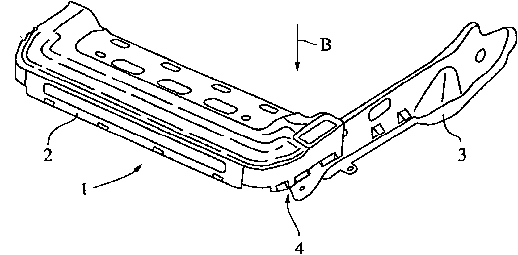
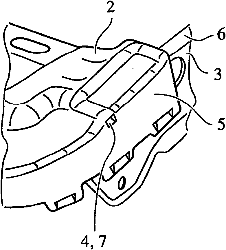
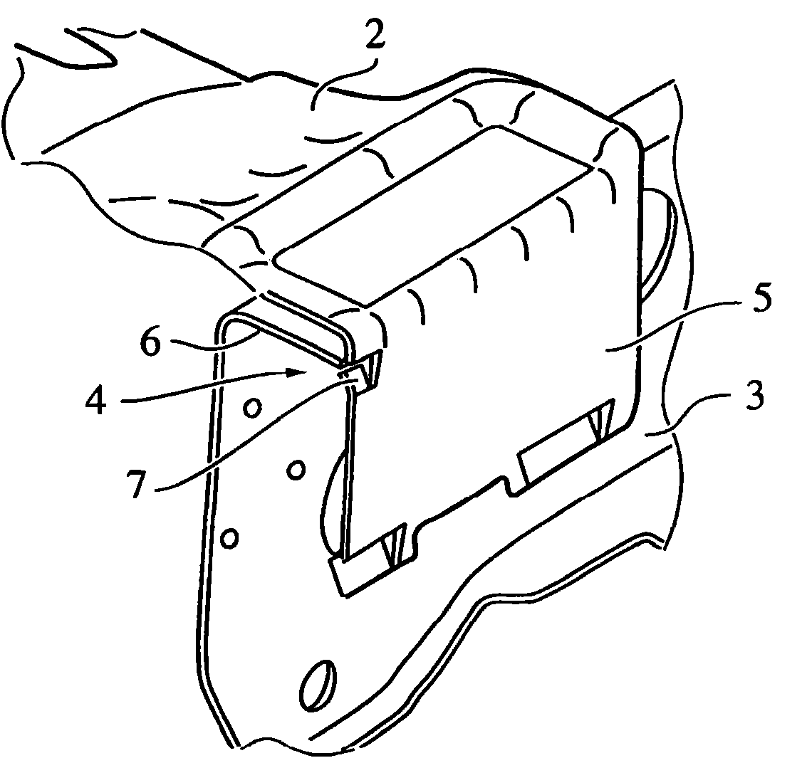
[0029] Figures 1 to 4 A first embodiment of a cross member 2 and a longitudinal member 3 as part of a seat structure 1 for a vehicle seat is schematically shown.

[0030] The seat structure 1 is preferably composed of different frame parts which have a main direction of extension and which are connected to one another to form a frame-shaped structure. In particular, the frame parts are fixed to one another in their final position by material bonding, preferably by welding; however, it is also possible to glue, rivet or screw the frame parts to one another. Prior to this final fastening, it is preferably provided that the frame parts are directly connected to one another in a form-fitting manner, in particular latched together. In the first embodiment, it is specified that a front cross member 2 of the seat structure 1 is configured such that it can be latched by pushing from above (ie in the Z direction of the vehicle) to Stringer 3 on. Through the latch engagement, not on...


PUM


Abstract

The invention relates to an assembly method for forming a seating structure for a vehicle seat, having a cross support (2) and a side support (3). For this purpose the cross support comprises at least one detent means (15), and the side support has at least one complementary detent means (8). During assembly, the detent means and the complementary detent means engage in each other, wherein the side support and the assembly support are positioned substantially perpendicular to each other. The cross support encompasses the side support for the engagement. The invention further relates to a seating structure produced in this way.

Description

technical field [0001] The invention relates to a method of assembly of a seat structure with cross members and longitudinal members for forming a vehicle seat. The transverse beam is provided with at least one stop means and the longitudinal beam is provided with at least one stop means complementary to said stop means. For assembly, said stop means and said complementary stop means are connected to each other by latches. Background technique [0002] The method of assembly of the stop means connected by latches is well known. For example, German patent application DE 10 2004 053 257 A1 discloses an arrangement for fixing a profile to a beam, the profile and / or the beam having at least one protruding fixing hook. A latch part with a bolt is for example disclosed as a fixing member. However, the known assembly methods have the disadvantage that the components to be assembled can easily become dislodged relative to one another during assembly. Due to this misalignment, th...

Claims


Application Information

Patent Timeline
Patent Type & Authority Patents(China)
IPC IPC(8): B60N2/68B60N2/90
CPCB60N2/682B60N2/68Y10T29/49936Y10T29/49968Y10T29/49826
Inventor L·米伦布罗克
Owner JOHNSON CONTROLS TECH CO
Why Eureka
Try Eureka