
Double-fan-blade coupling type wind energy generating set

A technology of generator set and double wind blades, which is applied in wind energy generation, wind turbine combination, wind turbine and other directions, can solve problems such as insufficient application and promotion of wind energy generators, and difficulties in wind energy branching.

Inactive Publication Date: 2011-06-29
胡国贤
View PDF0 Cites 0 Cited by
  • Summary
  • Abstract
  • Description
  • Claims
  • Application Information

AI Technical Summary

Problems solved by technology

[0002] Wind is a natural power source with great power. Great achievements have been made in the use of wind power generation at home and abroad, but there are technical difficulties in making full use of wind energy, and currently known wind power generators are difficult to start or fail at low wind speeds. The output power is insufficient, so the current wind power generator is not well applied and promoted

Method used


Image

  • Double-fan-blade coupling type wind energy generating set
  • Double-fan-blade coupling type wind energy generating set

Examples


Embodiment Construction

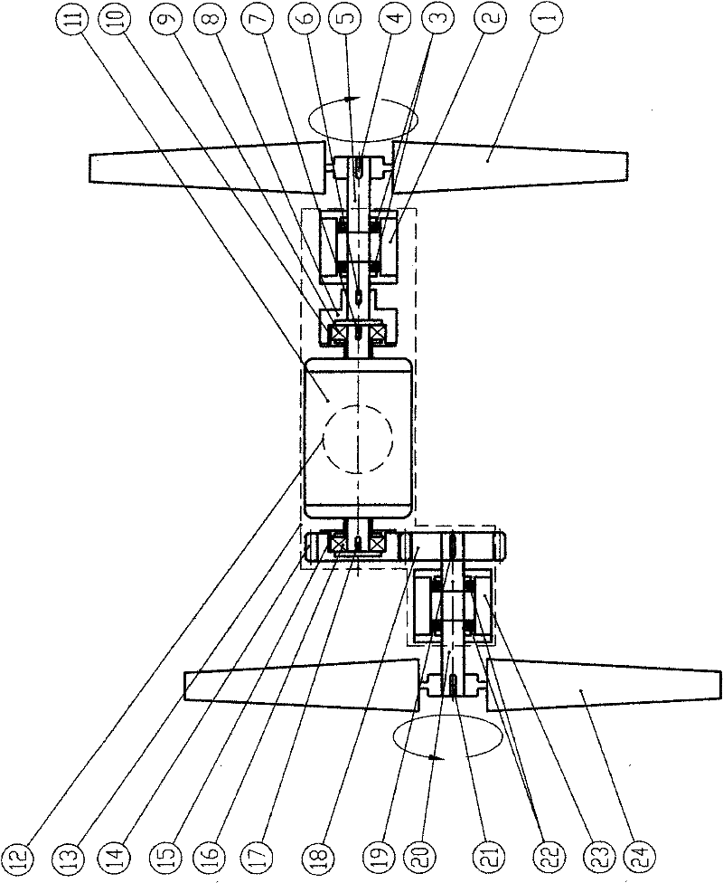
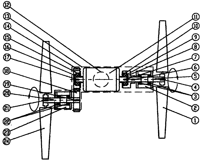
[0009] see figure 1 : the present invention's double-blade connecting-shaft wind energy generating set comprises base 13, forward-rotating wind blade 1, reverse wind blade 24, main shaft 5, one-way bearing 9, shaft coupling 8, reverse wind blade 24, main shaft 20, single To bearing 16, generator 11.

[0010] The forward-rotating fan blade 1 is connected to one end of the main shaft 5 through the shaft pin 4. The bearing 3 is installed in the middle of the main shaft 5. The bearing 3 is installed in the bearing seat 2. The coupling 8 is connected to the other end of the main shaft 5 through the shaft pin 6. The outer ring of the bearing 9 is connected with the inner hole of the shaft coupling through the shaft pin 10, and the inner ring of the one-way bearing 9 is installed on one end of the generator 11 shaft through the shaft pin 7.

[0011] The reversing vane 24 is connected to one end of the main shaft 20 through the shaft pin 21, the bearing 22 is installed in the middle ...


PUM


Abstract

The invention relates to a double-fan-blade coupling type wind energy generating set which has the essential point that both ends of the same generator shaft are provided with two sets of fan rotation blades comprising clockwise rotation fan blades and anticlockwise rotation fan blades, wherein the clockwise rotation fan blades are connected with one end of a main shaft A through a shaft pin; themiddle of the main shaft A is provided with a bearing which is arranged in a bearing seat A, while the other end of the shaft A is provided with a shaft pin and a coupling; an inner ring of the coupling is connected with an outer ring of a one-way bearing A through the shaft pin, and an inner ring of the one-way bearing A is connected with one end of the generator shaft through the shaft pin to rotate to drive a generator to generate electricity. The anticlockwise rotation fan blades are arranged at the end of a main shaft B, wherein the middle of the main shaft B is provided with a bearing which is connected with a bearing seat, and the other end of the main shaft B is connected with a reversing gear through a shaft pin; the reversing gear is engaged with a drive gear to rotate, and an inner through hole of the drive gear is connected with an outer ring of a one-way bearing B through a shaft pin; and an inner ring of the one-way bearing B is connected with the other end of the generator through a shaft pin to rotate. The generator is arranged between the clockwise rotation fan blades and the anticlockwise rotation fan blades.

Description

technical field [0001] The invention relates to a wind energy generator, in particular to a double fan blade coupling shaft type wind energy generator set. Background technique [0002] Wind is a natural power source with great power. Great achievements have been made in the use of wind power generation at home and abroad, but there are technical difficulties in making full use of wind energy, and currently known wind power generators are difficult to start or fail at low wind speeds. The output power is insufficient, so the current wind energy generators are not well applied and promoted. Contents of the invention [0003] The technical problem to be solved by the present invention is to overcome the defects of the prior art, and provide a double-blade coupled-shaft wind energy generating set with simple structure, fast start-up at low wind speed, increased output power at low wind speed, and stable operation at high wind speed. [0004] In order to achieve the purpose o...

Claims


Application Information

Patent Timeline
Patent Type & Authority Patents(China)
IPC IPC(8): F03D9/00F03D9/25
CPCY02E10/72
Inventor 胡国贤
Owner 胡国贤
Learn More