
Cylindrical backwash purifying device

A purification device and backwashing technology, which is applied to chemical instruments and methods, fixed filter element filters, filtration separation, etc., can solve the problems of low filtration efficiency, small filtration area, and small effective filtration area, so as to improve work efficiency, The effect of increasing the filtration area and ensuring continuity

Active Publication Date: 2010-02-03
郑州德奥科技有限公司
View PDF0 Cites 15 Cited by
  • Summary
  • Abstract
  • Description
  • Claims
  • Application Information

AI Technical Summary

Problems solved by technology

[0002] At present, the single-cylindrical filters sold on the market and used in various industries have the disadvantages of large volume, small filtration area, and low filtration efficiency, and must be stopped for replacement when replacing the filter screen, which affects the continuous operation of production; double-cylindrical Compared with the single cylindrical filter, the filter screen can be replaced without stopping the machine, but there is a filter screen on the cylindrical surface of the inlet side, which still has the defects of small effective filtration area and low filtration efficiency.
In addition, during the working process of the existing cylindrical filter, the material flow will form dead material somewhere, that is, the material that does not move, and these materials cannot be removed in time, which affects the filtering effect and product quality

Method used


Image

  • Cylindrical backwash purifying device
  • Cylindrical backwash purifying device
  • Cylindrical backwash purifying device

Examples


Embodiment Construction

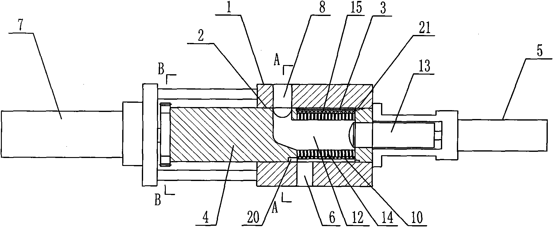
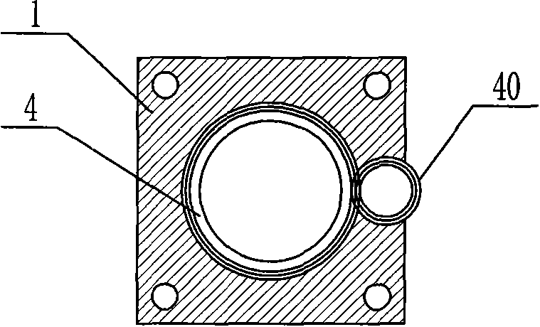
[0026] Such as figure 1 , figure 2 As shown, the cylindrical backwash purification device of the present invention includes a main body 1, a cylindrical through hole 2 is arranged in parallel in the main body 1, and a plunger 4 that is closely matched with it and can be axially slidably connected is arranged in the through hole 2 , the length of the plunger 4 is greater than the length of the through hole 2, and the front and rear of the main body 1 are respectively provided with a feed channel 6 and a discharge channel 8 connected with the through hole 2. The outer circle of the front part of the plunger 4 is concave inward and forms an annular cavity 10 with the inner wall of the through hole 2 respectively. The annular cavity 10 is connected with the feed channel 6. An "L"-shaped hole 12 connected to the discharge channel 8, in the "L"-shaped hole 12, a piston 13 slidingly connected to it is provided in front of the annular cavity 11, the piston 13 protrudes from the plun...


PUM


Abstract

The invention discloses a cylindrical backwash purifying device comprising a body and a plunger which is arranged in the body and can be connected in an axially sliding manner. The body is provided with a feeding passage and a discharge passage which are connected with a through hole. An outer circle at the front part of the plunger is recessed inwards, and together with the inner wall of the through hole, forms an annular empty cavity which is connected with the feeding passage. The plunger is axially provided with an L-shaped hole, which is connected with the discharge passage, in a direction from the front to the back. A recessed peripheral surface of the plunger is radially provided with a filter hole connected with the annular empty cavity and the L-shaped hole. The recessed peripheral surface of the plunger is connected with a detachable filter screen. A separating bar contacted with the inner wall of the through hole is axially arranged on the plunger and in the annular empty cavity. Semicircular grooves are arranged on the outer surface of the plunger and at two sides of the discharge passage. The cylindrical backwash purifying device has the advantages of reasonable design, simple structure, small volume, large effective filter area, good filter effect, no need of halt during cleaning or filter screen replacement, long continuous work time, high work efficiency and high product quality.

Description

technical field [0001] The invention relates to a fluid purification device, in particular to a cylindrical backwash purification device. Background technique [0002] At present, the single-cylindrical filters sold on the market and used in various industries have the disadvantages of large volume, small filtration area, and low filtration efficiency, and must be stopped for replacement when replacing the filter screen, which affects the continuous operation of production; double-cylindrical Compared with the single cylindrical filter, the filter screen can be replaced without stopping the machine, but there is a filter screen on the cylindrical surface of the inlet side, which still has the defects of small effective filtration area and low filtration efficiency. In addition, during the working process of the existing cylindrical filter, the material flow will form dead material somewhere, that is, the material that does not move, and these materials cannot be removed in t...

Claims


Application Information

Patent Timeline
Patent Type & Authority Applications(China)
IPC IPC(8): B01D29/31B01D29/66
Inventor 王训王振保王赞王操
Owner 郑州德奥科技有限公司
Learn More