
Curved hemostatic forceps for conveniently placing intrathoracic drain

A curved vascular forceps and drainage tube technology, applied in catheters, medical science, surgery, etc., can solve the problems of interfering with diagnosis and treatment, waste, increase costs, etc., and achieve the effect of improving operation efficiency and reducing patient pain.

Inactive Publication Date: 2010-02-03
李强 +2
View PDF0 Cites 4 Cited by
  • Summary
  • Abstract
  • Description
  • Claims
  • Application Information

AI Technical Summary

Problems solved by technology

However, these designs also have some disadvantages: first, the metal nozzle or metal guiding stylet has the potential risk of damaging tissues and organs in the chest cavity after entering the chest cavity; second, the drainage tube is a disposable consumable , these designs increase the complexity of the drainage tube, increase the cost, lead to increased medical expenses and patient burden, and too many accessories cause a lot of waste; third, especially the drainage tube with a metal nozzle, a certain period of time Built up in the chest cavity, can interfere with diagnosis and treatment

Method used


Image

  • Curved hemostatic forceps for conveniently placing intrathoracic drain
  • Curved hemostatic forceps for conveniently placing intrathoracic drain
  • Curved hemostatic forceps for conveniently placing intrathoracic drain

Examples


Embodiment Construction

[0010] In order to clearly illustrate the technical characteristics of this solution, the following describes this solution through a specific implementation in conjunction with the accompanying drawings.

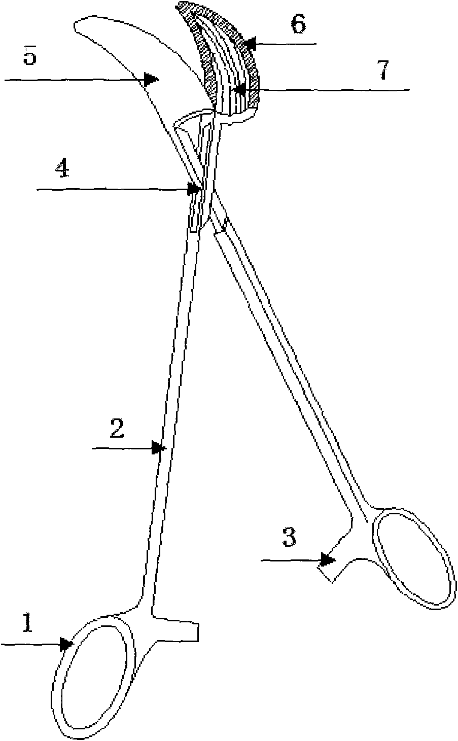
[0011] Such as figure 1 As shown, the vascular forceps described in the present invention is composed of a handle ring (1), a lock (2), a forceps handle (3), a shaft (4), and a forceps leaf (5). On the alveolar bed (6) surface of the two pliers blades, there are symmetrical concave surfaces (7), and the concave surface is semi-elliptical along the cross section of the pliers blades. The tooth pattern on the concave surface of the alveolar bed is a vertical pattern along the longitudinal axis of the pliers blade, and the other part is a horizontal pattern.

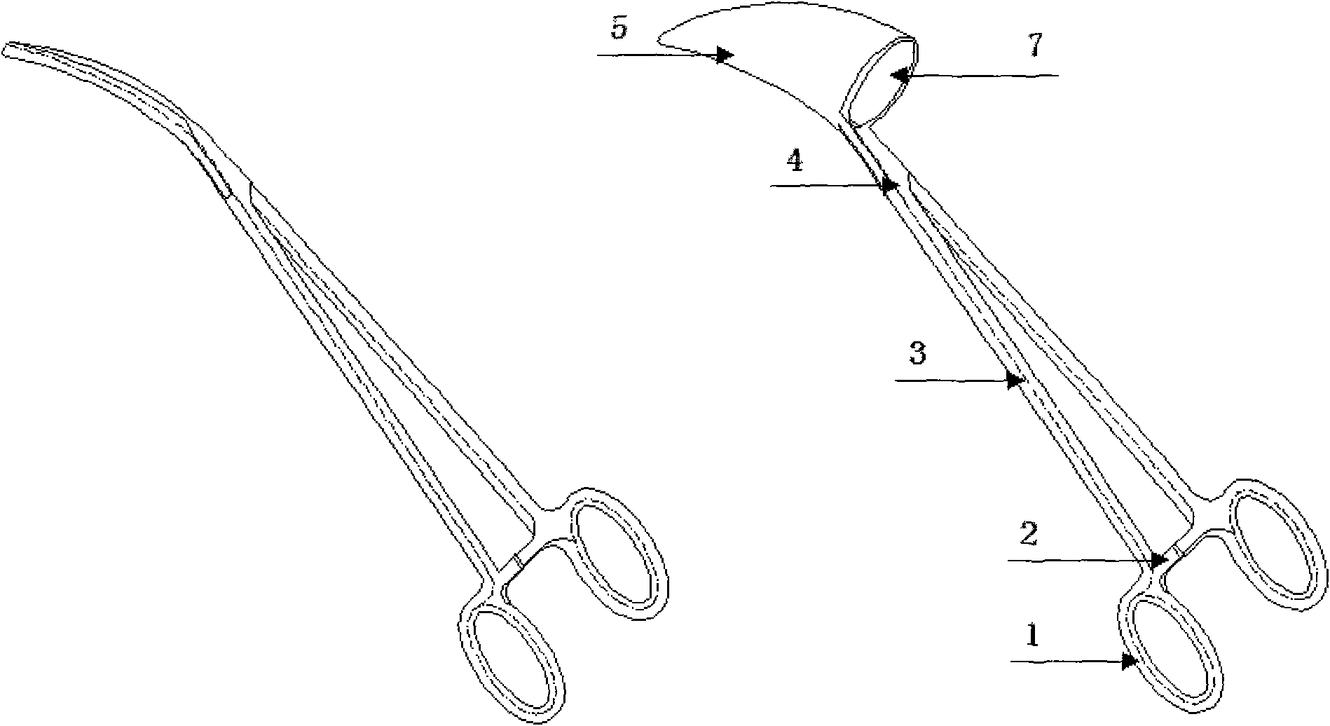
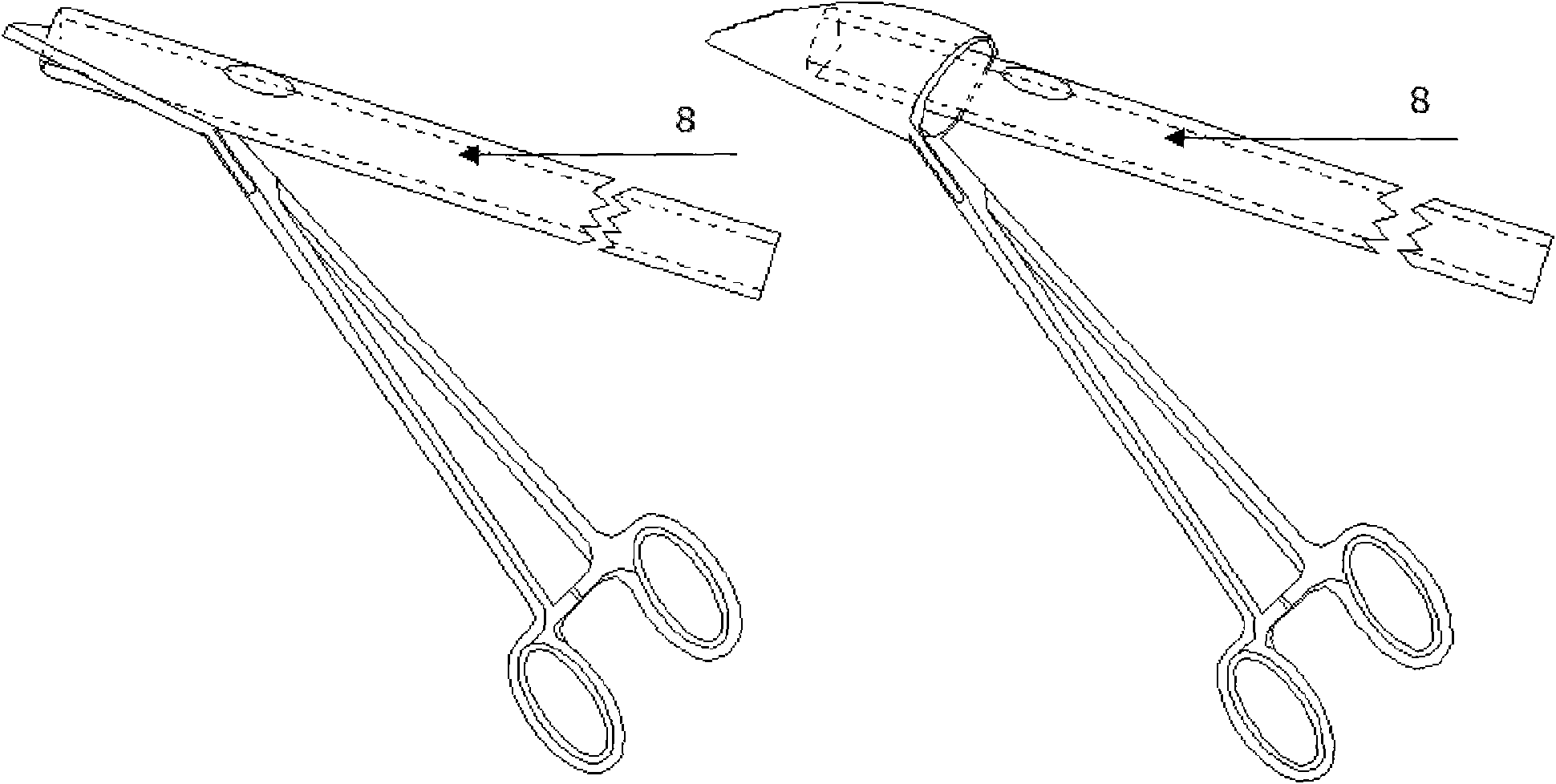
[0012] Such as figure 2 , image 3 As shown, the left of the figure is a common vascular clamp, and the right is the vascular clamp described in the present invention that is convenient for placing a chest drainage tube. W...


PUM


Abstract

The invention discloses a curved hemostatic forceps for conveniently placing an intrathoracic drain. The curved hemostatic forceps conveniently guides the intrathoracic drain into the thoracic cavitysmoothly, avoids excessive force or repeatedly using the hemostatic forceps for exploration, alleviates the sufferings of patients, and improves operation efficiency. The hemostatic forceps consists of grip rings, a buckle, a forceps handle, an axial ring and forceps leaves. Alveolus bed surfaces of two forceps leaves are provided with symmetrical concave surfaces, the concave surfaces are of semiellipse shape along cross sections of the forceps leaves, the concave surfaces of the two forceps leaves form a tubular structure with the cross section of oval shape when the hemostatic forceps is closed, and a tubular head is of conical shape and points at the front end of the forceps leaves; in such a way, a clamped cylindrical intrathoracic drain can slightly deform, which is favorable for exact clamping. Insection at other part of the alveolus bed is transverse insection, and insection at the concave surfaces part is vertical insection along vertical axis of the forceps leaves, which caneffectively clamp the intrathoracic drain tightly, and does not coarsen and damage the smooth surface of the intrathoracic drain. The head of the forceps can support the chest-wall muscular layer andparietal pleura, guide the orifice of the intrathoracid drain clamped by the forceps leaves into the thoracic cavity smoothly, and then the forceps is loosened, and leaves the thoracic cavity. The conical head part of the tubular structure can exactly clamp intrathoracic drains of different diameters, and avoid bringing out the intrathoracic drains when the hemostatic forceps is removed.

Description

Technical field [0001] The invention belongs to the field of medical equipment, and designs a curved blood vessel clamp which is convenient for placing a chest drainage tube. Background technique [0002] Closed thoracic drainage is the most common surgical operation in thoracic surgery. Curved vascular clamps are usually used to clamp the head of the drainage tube and introduce it into the chest cavity. Under normal circumstances, the vascular clamp is easy to enter during exploration, but it is not easy to enter after clamping the drainage tube; or the tip of the forceps can enter smoothly, but the drainage tube orifice is often stuck in the chest wall tissue. This is mainly because the entrance to the thoracic cavity was initially formed after the vascular clamp was separated and broken through. The parietal tissue is elastic and recovers quickly after being expanded. The drainage tube orifice is relatively large, especially after the tube orifice is flattened by the vascular ...

Claims


Application Information

Patent Timeline
IPC IPC(8): A61B17/00A61M25/01
Inventor 李强张雷刘爱军
Owner 李强
Learn More