Optical manipulation device

A control device, an optical technology, used in sports accessories, instruments, electrical and digital data processing, etc., can solve problems such as damage, malfunction, and high price of capacitive control devices, and achieve good reliability and not easy to damage.

Inactive Publication Date: 2010-01-20
PIXART IMAGING INC
View PDF0 Cites 7 Cited by
  • Summary
  • Abstract
  • Description
  • Claims
  • Application Information

AI Technical Summary

Problems solved by technology

The resistive control device has the disadvantage of low sensitivity, so it is easy to be damaged due to excessive force applied by the user
Capacitive control devices have the disadvantages of being expensive and prone to malfunction due to factors such as static electricity or humidity

Method used


Image

  • Optical manipulation device
  • Optical manipulation device
  • Optical manipulation device

Examples


Embodiment Construction

[0043] In order to further explain the technical means and effects of the present invention to achieve the intended purpose of the invention, the specific implementation, features and effects of the optical control device proposed according to the present invention will be described in detail below in conjunction with the accompanying drawings and preferred embodiments. The description is as follows.

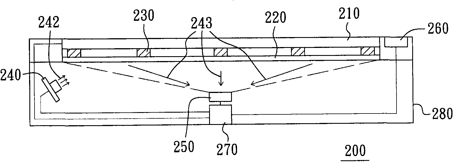
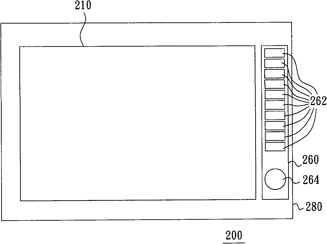
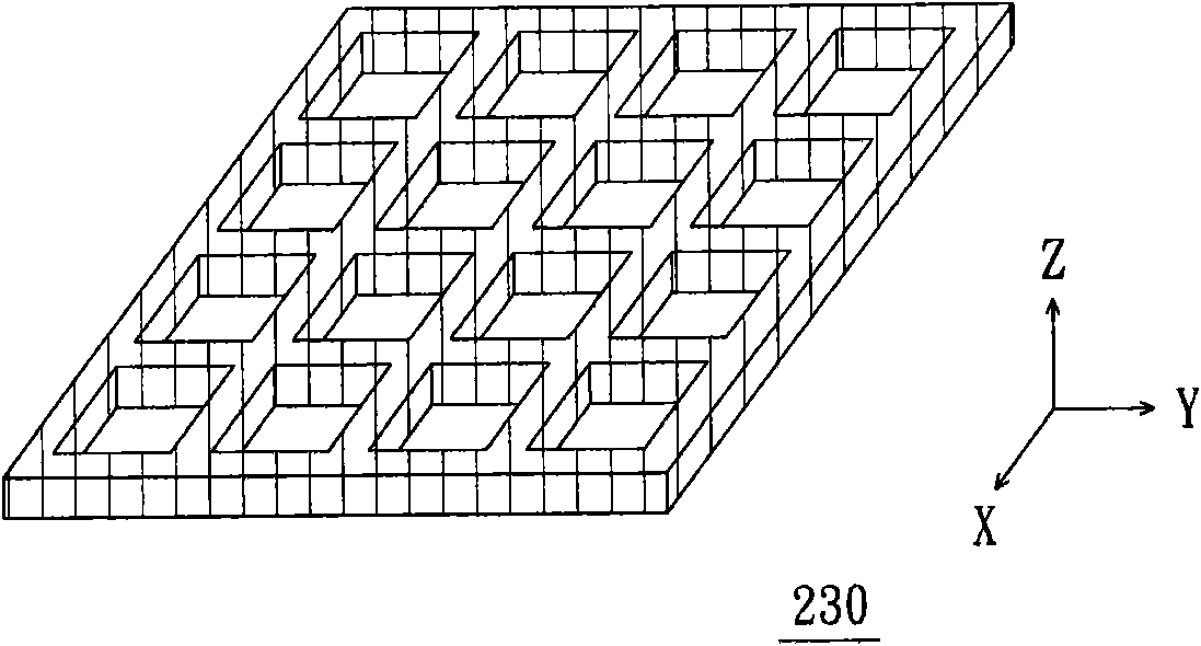
[0044] figure 1 is a schematic diagram of an optical manipulation device according to an embodiment of the present invention, figure 2 yes figure 1 The top view of the optical control device, and image 3 yes figure 1 Stereogram of the deformation element in . Please refer to Figure 1 to Figure 3 , the optical control device 200 of this embodiment can be connected to an electronic device, such as a computer, a television, a game machine, etc. The optical control device 200 includes a display panel 210 , a transparent support plate 220 , a deformation unit 230 , a light s...


PUM


Abstract

The invention relates to an optical manipulation device, which comprises a display panel, a transparent supporting plate, a deformation unit, a light source, an image sensing module, a function selecting module and a processing module. The deformation unit is placed between the transparent supporting plate and the display panel, and has a pattern structure. When a user applies pressure on the display panel, the deformation unit produces deformation; and when pressure application to the display panel is stopped, the deformation unit recovers to the primary shape. The light source provides light beams to the deformation unit; and the sensing field of the image sensing module covers the whole deformation unit. The function selecting module is placed beside the display panel, and is provided with a plurality of function selecting keys for the user to select a predetermined function. The processing module is electrically connected with the display panel, the function selecting module, the image sensing module and the light source. The processing module facilitates the display panel to display a predetermined picture corresponding to the predetermined function.

Description

technical field [0001] The invention relates to a control device, in particular to an optical control device. Background technique [0002] With the advancement of flat display technology, more and more electronic products have screens, and many electronic products are operated by moving a cursor on the screen. There are many kinds of control devices used to move the cursor, common ones are resistive control devices and capacitive control devices. The resistive control device has the disadvantage of low sensitivity, so it is easy to be damaged due to excessive force applied by the user. Capacitive control devices have the disadvantages of being expensive and prone to malfunction due to factors such as static electricity or humidity. [0003] On the other hand, in addition to the traditional joystick, the control device used to control video games has recently been developed to allow players to use their feet to control the control device. The player can place both feet on...

Claims


Application Information

Patent Timeline
IPC IPC(8): G06F3/042A63F13/06A63F13/213A63F13/24
Inventor 林卓毅徐尧庆
Owner PIXART IMAGING INC
Why Eureka
Try Eureka