Coriolis acceleration test device
A technology of Coriolis acceleration and testing device, which is applied in the field of experimental teaching to achieve the effect of stable performance and high measurement accuracy
Inactive Publication Date: 2010-01-13
EAST CHINA JIAOTONG UNIVERSITY
View PDF1 Cites 17 Cited by
- Summary
- Abstract
- Description
- Claims
- Application Information
AI Technical Summary
Problems solved by technology
[0004] The purpose of the present invention is to solve the Coriolis acceleration demonstration problem in the synthetic motion that implicates motion is to rotate, and solves the Coriolis acceleration experiment test problem
Method used
View moreImage
Smart ImageViewing Examples

Examples
Embodiment 2
[0051] Referring to the accompanying drawings, the device described in the present embodiment does not have a lifting rod 3, and other components are structured as shown in the accompanying drawings.
Login to View More PUM
 Abstract
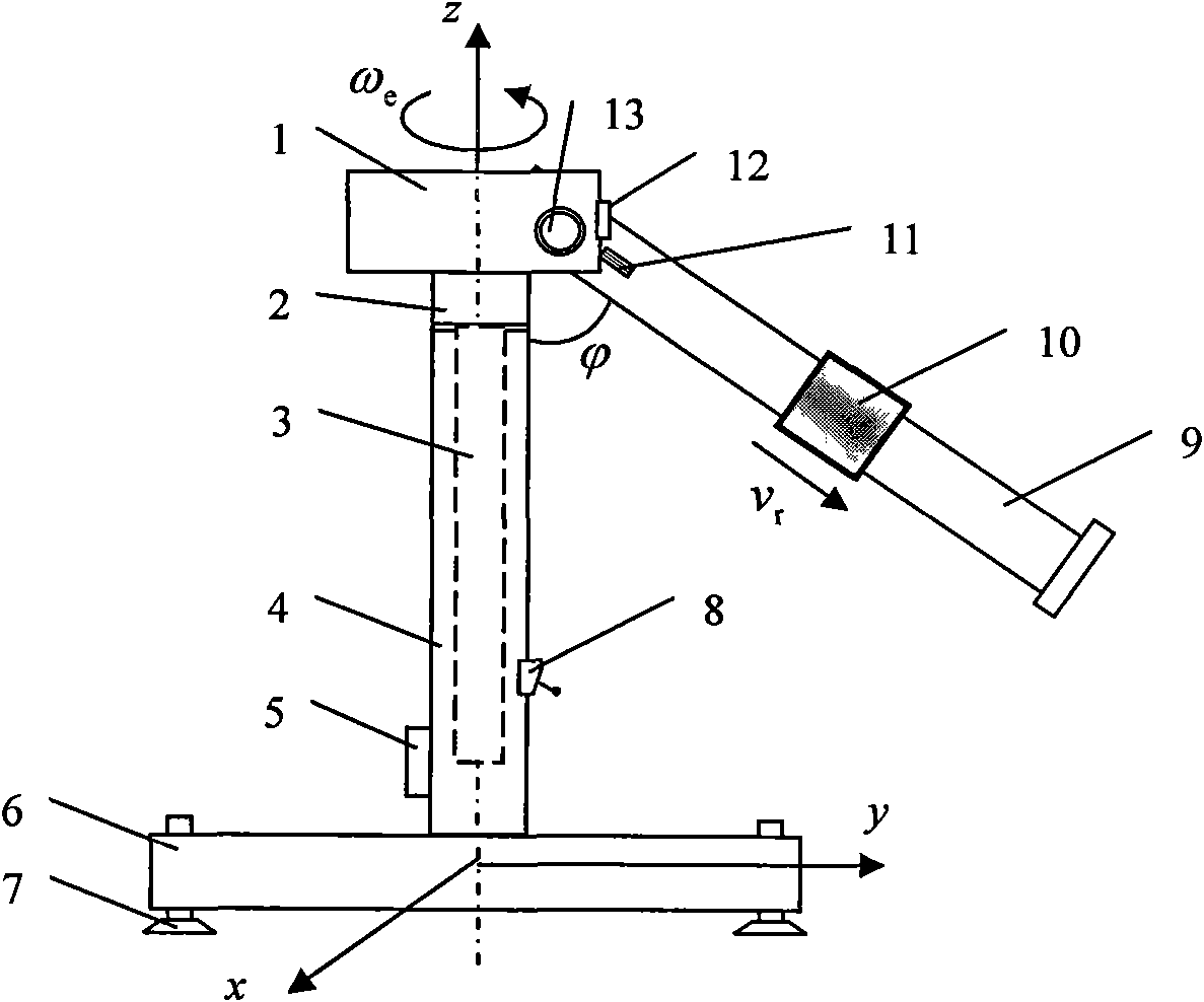
The invention relates to a coriolis acceleration test device which comprises a main frame, a fixed support column on the main frame, a rotary node on the fixed support column, an elevating rod, a light flexible rod and a large-mass sliding block sleeved on the light flexible rod, wherein the elevating rod is arranged in the fixed support column and is capable of moving vertically under the driving of an adjustable motor, and the included angle of the light flexible rod can be adjusted on the rotary node; the fixed support column is provided with an electrical primer, a limit switch, the adjustable motor and a driving mechanism, wherein the adjustable motor can drive the rotary node to rotate around a rotation shaft z, an angle sensor and a linear displacement sensor are arranged on the rotary node, one end of the light flexible rod is provided with a two-sided strain gauge, and the electrical primer is connected with a signal processor and a calculation device. The invention is helpful for students to vividly, directly and concretely understand and grasp the concept of coriolis acceleration and has high and simple measurement accuracy, dynamic and stable performance; measurement results can be conveniently transmitted to a computer for calculation and analysis so as to conclude required data and diagrams, and thus, the invention enables tests to be diversified and interesting.
Description
technical field [0001] The invention belongs to the technical field of experiment teaching, and in particular relates to a theoretical mechanics experiment testing device. Background technique [0002] Coriolis acceleration was discovered by Coriolis in 1832, so it is named as Coriolis acceleration (Coriolis acceleration), referred to as Coriolis acceleration. Coriolis acceleration is shown in natural phenomena. As far as the earth is concerned, even if the earth’s revolution around the sun is not considered, the earth will also rotate around the earth’s axis. The earth is a moving reference system, and the motion of objects on the earth relative to the earth is a composite motion of implicated motion as rotation, and there will be Coriolis Acceleration exists. The angular velocity of the earth's rotation is relatively small, and the influence of its rotation can be ignored in general; but in some cases, it must be taken into consideration. For example, in the northern he...
Claims
Login to View More Application Information
Patent Timeline
 IPC IPC(8): G09B23/10G01P15/12
Inventor 朱爱华朱成九
Owner EAST CHINA JIAOTONG UNIVERSITY
Features
- R&D
- Intellectual Property
- Life Sciences
- Materials
- Tech Scout
- Unparalleled Data Quality
- Higher Quality Content
- 60% Fewer Hallucinations
Learn More Browse by: Latest US Patents, China's latest patents, Technical Efficacy Thesaurus, Application Domain, Technology Topic, Popular Technical Reports.
© 2025 PatSnap. All rights reserved.Legal|Privacy policy|Modern Slavery Act Transparency Statement|Sitemap|About US| Contact US: help@patsnap.com