
Method, control device and drive device for detaching a charge stuck to the inner wall of a grinding pipe

A technology of a driving device and a control device, which is applied to the driving device of the grinding tube and the field of the tube mill, can solve the problem of time-consuming and the like

Inactive Publication Date: 2009-08-05
SIEMENS AG
View PDF5 Cites 3 Cited by
  • Summary
  • Abstract
  • Description
  • Claims
  • Application Information

AI Technical Summary

Problems solved by technology

Removal of stuck charges is subject to extremely high and mostly manual labor overhead and is very time consuming

Method used


Image

  • Method, control device and drive device for detaching a charge stuck to the inner wall of a grinding pipe
  • Method, control device and drive device for detaching a charge stuck to the inner wall of a grinding pipe
  • Method, control device and drive device for detaching a charge stuck to the inner wall of a grinding pipe

Examples


Embodiment Construction

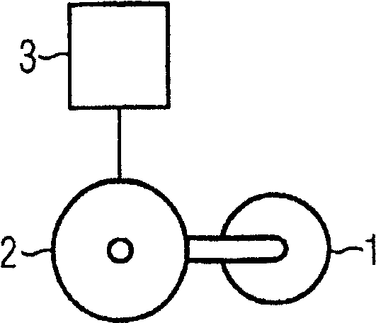
[0027] figure 1 A schematic structure of, for example, a tube mill for grinding ore is shown. The tube mill has a grinding tube 1 connected to a drive 2 . Furthermore, there is a control device 3 which sends control or regulating signals to the drive device 2 . The control device 3 can also receive and process signals, for example measurement signals from the drive device 2 or other components of the tube mill. The grinding tube 1 is preferably formed in the form of a drum. The tube mill has a support device (not shown in detail in the drawing) for grinding the tube 1 .

[0028] The drive 2 of the tube mill has at least one electric motor, for example designed as a ring motor. The electric motor is coupled to a converter, not shown in detail. The characteristic of the electric motor as a ring motor is that it can drive the grinding tube 1 without a gear and thus enables a particularly robust operation of the tube mill.

[0029] The drive 2 is preferably designed as a fie...


PUM


Abstract

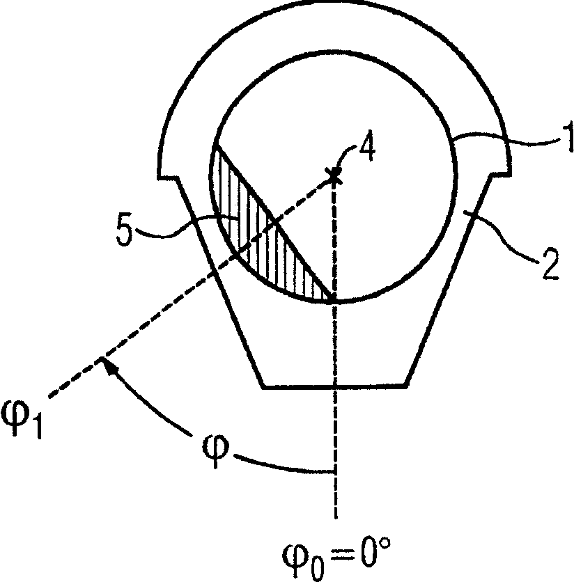
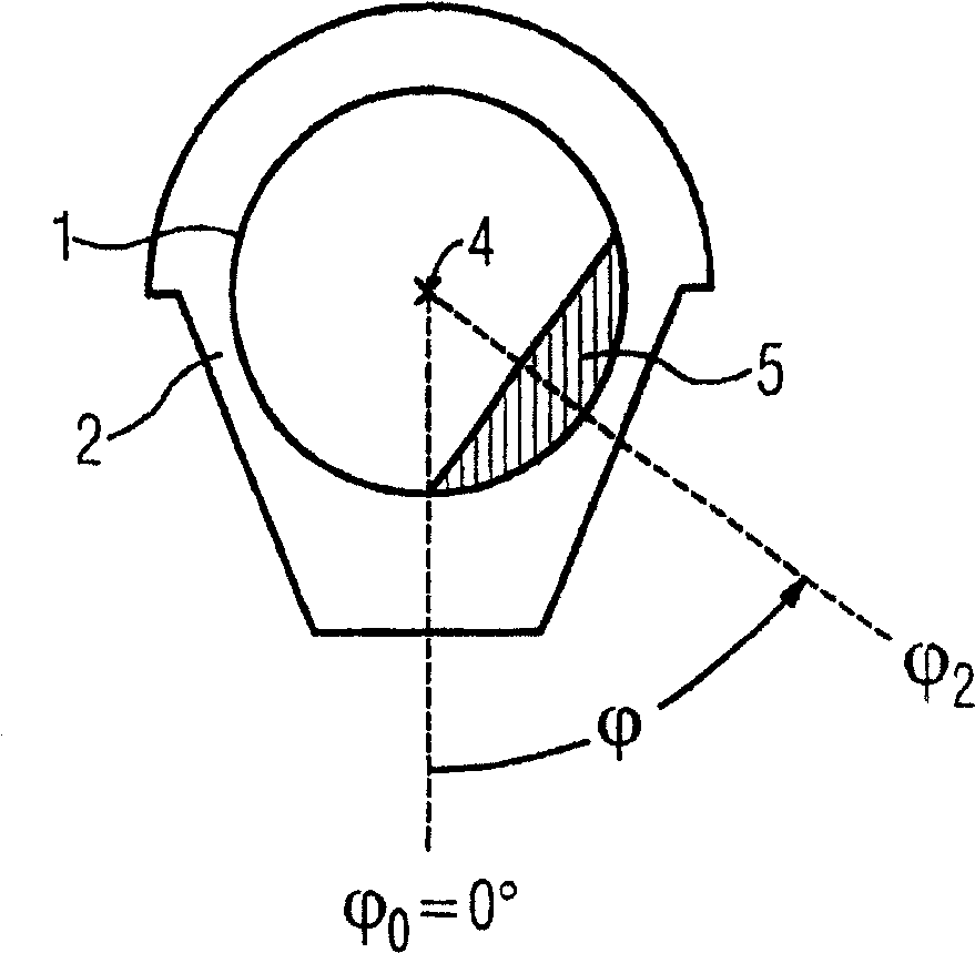
The invention relates to a method for removing adhered charge (5) from the inner wall of a grinding tube (1), wherein the targeted removal of adhered charge (5) is controlled by a control device (3) Control the drive device (2) of the grinding tube (1). The grinding tube (1) is rotated in such a targeted manner that the adhered charge (5) is removed from the grinding tube (5) by changing the rotational speed of the grinding tube (1) several times and, if necessary, by sudden braking of the grinding tube (1). The inner wall of the grinding tube (1) is peeled off. The maximum rotation angle (φ) of the grinding tube (1), which is generally determined by the material, is not exceeded in order to avoid an uncontrolled fall of the stuck charge (5). The invention eliminates the need for labor-intensive and time-consuming methods to remove stuck charges (5), since these can be removed by the drive (2) using the same electric motor that also drives the grinding tube (1) during the grinding operation. .

Description

technical field [0001] The invention relates to a method for removing adhering material from the inner wall of a grinding tube, in particular of a tube mill, a control device for a grinding tube drive and a grinding tube drive. Furthermore, the invention relates to a tube mill. Background technique [0002] Tube mills are mainly used for grinding materials such as ores. It is not uncommon for the operation of the tube mill to be interrupted for a longer period of time and the tube mill to be shut down. This is the case, for example, for maintenance reasons. During tube mill shutdown, material within the grinding tube of the tube mill may solidify and stick to the inner wall of the grinding tube. This cohesive cured material attached to the inner wall of the grinding tube is referred to as cohesive charges or also "frozen charges". If the tube mill is restarted after a prolonged shutdown, there is the risk that the adhered charge falls off the grinding tube at a great hei...

Claims


Application Information

Patent Timeline
Patent Type & Authority Patents(China)
IPC IPC(8): B02C17/18B02C17/24B02C23/04B02C25/00
CPCB02C25/00B02C17/1805B02C17/24Y10T29/49817B02C23/04Y10T29/53687
Inventor 诺伯特·贝克斯蒂芬·斯米茨库尔特·蒂施勒
Owner SIEMENS AG
Learn More