
Heat-pump water-heater water tank

A technology for heat pump water heaters and water tanks, which is applied to fluid heaters, lighting and heating equipment, etc., can solve the problems of hidden dangers in use, the large difference between the display temperature and the water outlet temperature, etc., and achieve the effect of improving the safety of use.

Inactive Publication Date: 2010-01-13
GUANGDONG CHIGO AIR CONDITIONING
View PDF0 Cites 4 Cited by
  • Summary
  • Abstract
  • Description
  • Claims
  • Application Information

AI Technical Summary

Problems solved by technology

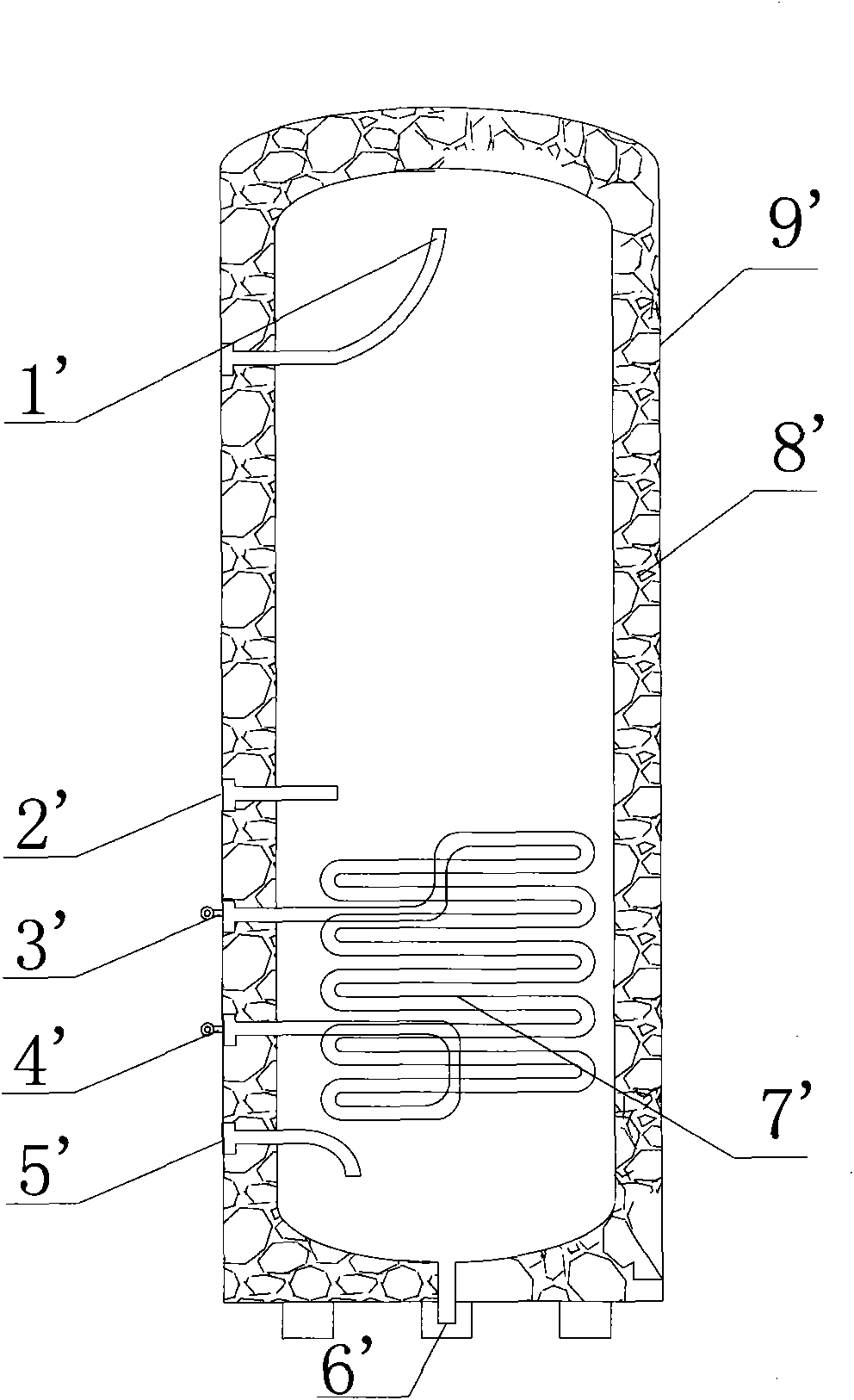
Because the water in the water tank is stratified, that is, the water with higher temperature will be at the top of the water tank, and the water with lower temperature will be at the bottom of the water tank. When the cold water is added to the vicinity of the temperature probe 2', the detected water temperature will be relatively low, but the actual water outlet 1' will have a relatively high outlet temperature, resulting in a large difference between the displayed temperature and the outlet water temperature, resulting in potential safety hazards

Method used


Image

  • Heat-pump water-heater water tank
  • Heat-pump water-heater water tank

Examples


Embodiment Construction

[0012] In order for those skilled in the art to better understand the technical solutions provided by the present invention, the following will be described in conjunction with specific embodiments.

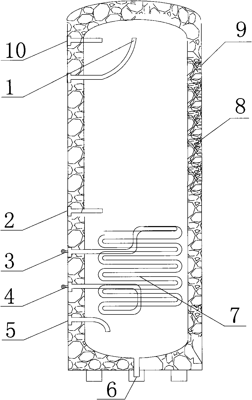
[0013] See figure 2 , which is a schematic structural view of the water tank of the heat pump water heater in the present invention.

[0014] The heat pump water heater water tank provided by the present invention includes a water outlet 1, a temperature probe 10, a refrigerant inlet 3, a refrigerant outlet 4, a water inlet 5, a sewage outlet 6, a heat exchange coil 7, a casing 9 and an insulation layer 8, and the temperature probe 10 is set On the same horizontal position as the water outlet 1, the temperature probe 10 is connected with the remote control display for displaying the temperature of the water outlet. The water tank of the heat pump water heater also includes a second temperature probe 2. The second temperature probe 2 is arranged at the position near the heat exc...


PUM


Abstract

The invention discloses a heat-pump water-heater water tank comprising an outer shell, a water inlet, a water outlet, a heat exchange coil and a temperature detecting device, wherein the temperature detecting device is arranged on the same horizontal position of the water outlet. The heat-pump water-heater water tank can make display temperature consistent with water outlet temperature, thereby increasing use safety.

Description

technical field [0001] The invention relates to the field of water heaters, in particular to a heat pump water heater water tank. Background technique [0002] At present, the water tank of the heat pump water heater used at home has only one temperature probe, which is used to detect the water temperature in the water tank and control the operation status of the compressor. See Figure 1 , which is a structural schematic diagram of a water tank of a heat pump water heater in the prior art. The heat pump water heater water tank in the prior art includes a water outlet 1', a temperature probe 2', a refrigerant inlet 3', a refrigerant outlet 4', a water inlet 5', a sewage outlet 6', a heat exchange coil 7', a casing 9' and The insulation layer 8' and the temperature probe 2' are generally set close to the top of the heat exchange coil 7', and the heat exchange coil 7' is placed at the bottom of the water tank, so that the position of the temperature probe 2' is set in the mid...

Claims


Application Information

Patent Timeline
Patent Type & Authority Applications(China)
IPC IPC(8): F24H9/00F24H9/20F24H9/02
Inventor 崔严鹏李大振殷银坤李燕
Owner GUANGDONG CHIGO AIR CONDITIONING
Learn More