
Hydraulic tensioning element for a traction mechanism drive

A driver and component technology, applied in the direction of transmission, belt/chain/gear, mechanical equipment, etc., can solve the problem of insufficient piston accuracy, and achieve the effect of improving guiding accuracy and mechanical vibration damping

Inactive Publication Date: 2014-06-11
SCHAEFFLER TECH AG & CO KG
View PDF2 Cites 0 Cited by
  • Summary
  • Abstract
  • Description
  • Claims
  • Application Information

AI Technical Summary

Problems solved by technology

[0004] In such conventional hydraulic tensioning elements, the precision of the piston guidance is insufficient

Method used


Image

  • Hydraulic tensioning element for a traction mechanism drive
  • Hydraulic tensioning element for a traction mechanism drive
  • Hydraulic tensioning element for a traction mechanism drive

Examples


Embodiment Construction

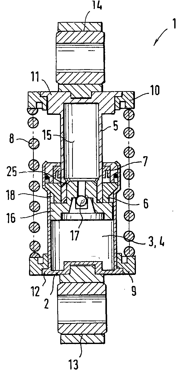
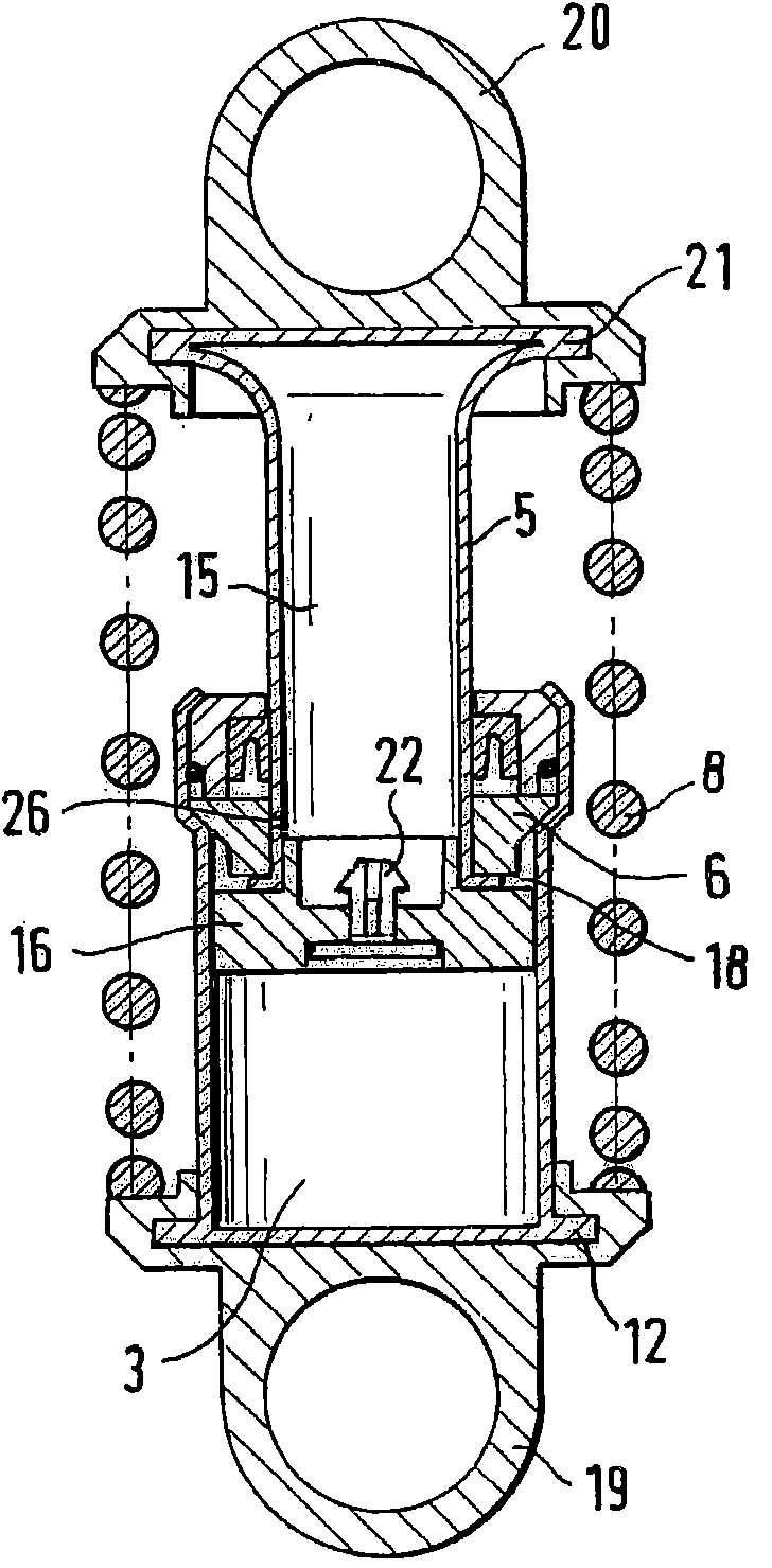
[0019] figure 1 A longitudinal section through a first exemplary embodiment of the hydraulic tensioning element 1 is shown. The tensioning element 1 comprises a bowl-shaped cylinder 2 which is produced by deep drawing and which is filled with a hydraulic fluid 4 . The piston 5 passes through the opening of the cylinder 2 , wherein the piston 5 made of stainless steel is radially supported by a guide ring 6 and sealed by a piston rod seal 7 which is arranged in a stationary manner In the housing of cylinder 2.

[0020] The cylinder 2 and the piston 5 are surrounded by a spring element in the form of a compression spring 8 which is supported on its end face by fastening elements in the form of spring support elements 9 , 10 which are supported on the base 11 of the piston 5 Or on the collar 12 of the cylinder 2. The fastening holes 13 , 14 are attached to the bottom 11 of the piston 5 or to the end face of the cylinder 2 , for example by gluing.

[0021] Located inside the p...


PUM


Abstract

Clamping element comprises a cylinder (2) having a seal (7) fixed in a housing and a guiding ring (6) arranged between a plunger (5) and the cylinder. An annular chamber (18) which is delimited by the guiding ring, the inner side of the cylinder and the outer side of the plunger is connected to a supply chamber (15) in the plunger via fluid channels (25, 26). Preferred Features: The plunger is made from stainless steel. A spring element arranged between the cylinder and plunger is a pressure spring (8) having an inner diameter which is larger than the outer diameter of the cylinder.

Description

technical field [0001] The invention relates to a hydraulic tensioning element for a traction implement drive, the tensioning element having a cylinder, an axially movable piston bound in the cylinder, a spring element arranged between the cylinder and the piston, constructed in the cylinder A compression chamber and a hydraulic fluid reserve chamber built in the piston and a valve capable of exchanging hydraulic fluid between the compression chamber and the reserve chamber depending on the adjustment movement of the piston. Background technique [0002] Hydraulic tensioning elements are used in traction means drives of internal combustion engines for tensioning traction means such as belts or chains. The tensioning element comprises a cylinder designed as a stationary and pivotable housing part and a piston connected directly or indirectly to the tensioning pulley, a spring element being arranged between the cylinder and the piston. The spring element can be designed as a ...

Claims


Application Information

Patent Timeline
Patent Type & Authority Patents(China)
IPC IPC(8): F16H7/08F16H7/12
CPCF16H2007/0806F16H2007/0859F16H7/0836
Inventor 贝恩德·哈特曼维尔纳·彼得里
Owner SCHAEFFLER TECH AG & CO KG
Learn More