
Walking claw with shockproof hammer accommodating function

An anti-vibration hammer and function technology, which is applied in the field of line inspection robots, can solve the problems of reducing the feasibility of inspection by line inspection robots, less types of obstacles that can be crossed, and short continuous operation time, so as to achieve precise and rapid control of the moving position of small wheels. , Easy and fast installation, good telescopic stability

Active Publication Date: 2021-03-09
GUIZHOU POWER GRID CO LTD
View PDF8 Cites 0 Cited by
  • Summary
  • Abstract
  • Description
  • Claims
  • Application Information

AI Technical Summary

Problems solved by technology

[0002] At present, the existing line inspection robots still have the disadvantages of heavy weight and short continuous operation time, and there are few types of obstacles that can be crossed, especially the jumpers between tension towers, which reduce the use of line inspection robots for inspections. Feasibility
The Chinese patent application (application number 2019112042313) discloses a high-voltage transmission line patrol robot, which adopts the front wheel hub motor and the rear hub motor to be hooked on the wire in reverse, and the front claw and the rear claw are reversely mounted on the wire Above and between the front hub motor and the rear hub motor, the front and rear dropouts have more structural components, making it harder to control and harder to climb over the shock hammer

Method used


Image

  • Walking claw with shockproof hammer accommodating function
  • Walking claw with shockproof hammer accommodating function
  • Walking claw with shockproof hammer accommodating function

Examples


Embodiment 1

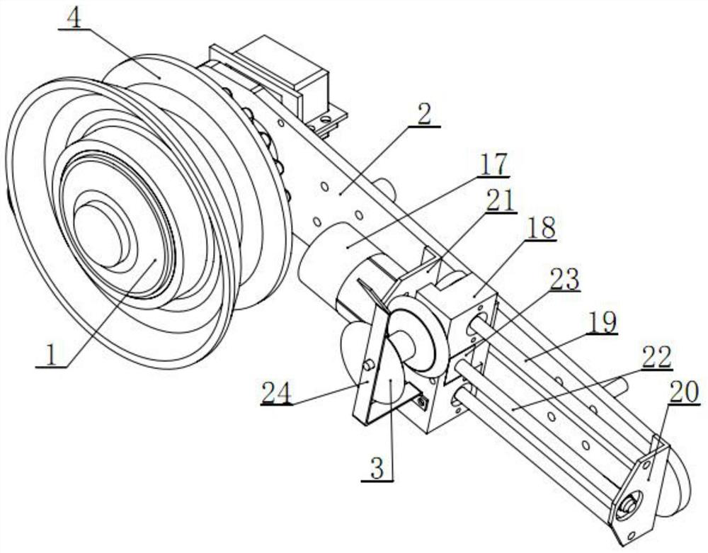
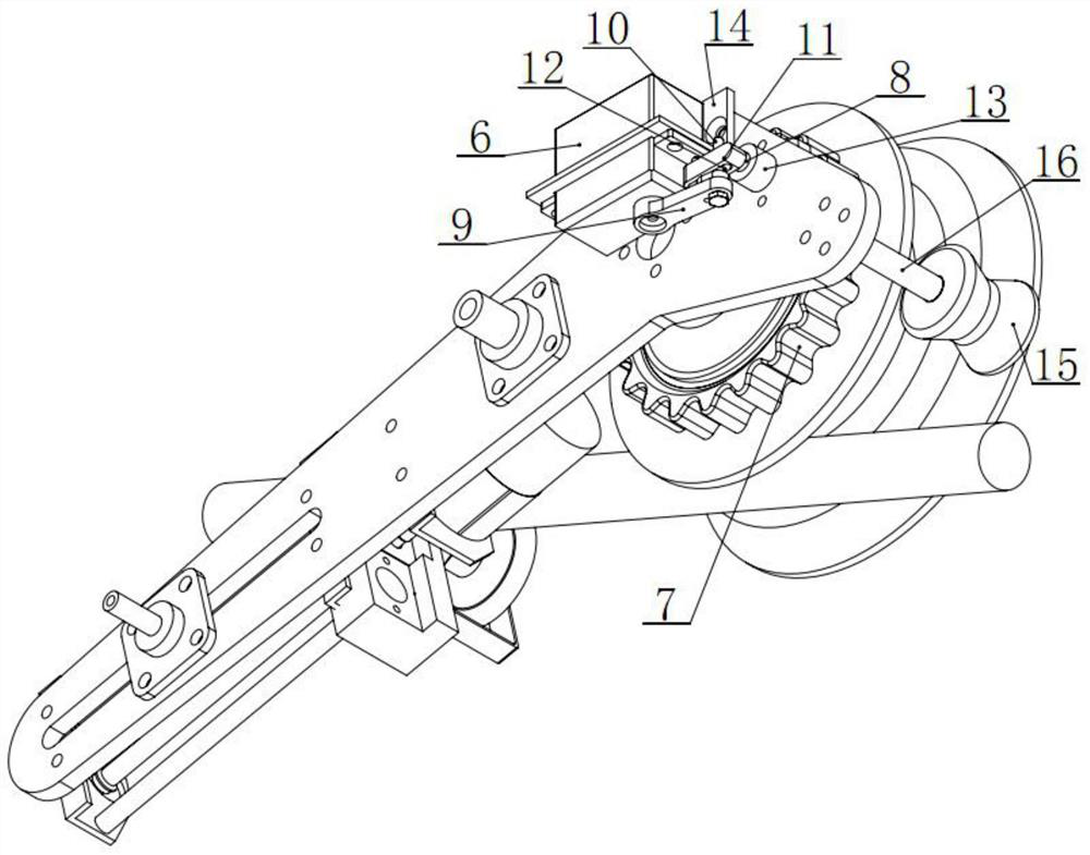
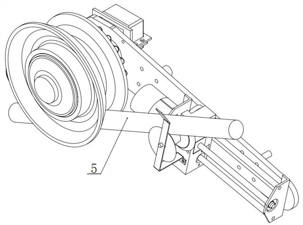
[0031] Embodiment 1: as Figure 1-6 As shown, a walking claw with the function of accommodating a shockproof hammer includes a hub motor 1, a side plate 2 and a small wheel 3. The hub motor 1 is covered with a rubber layer 4 with a cylindrical surface in the shape of an annular groove, and one end of the hub motor 1 is fixed. Connected to the front side of the side plate 2, the side plate 2 is also rotatably mounted with a small wheel 3 with a cylindrical surface in the shape of an annular groove, the upper side of the groove of the small wheel 3 and the lower side of the groove of the rubber layer 4 can contact the wire 5 , the small wheel 3 is connected to the telescopic device through the small wheel frame 24, the telescopic device is installed on the side plate 2, the side plate 2 is a bending structure, including a front inclined section and a rear inclined section, and the hub motor 1 is installed on the side plate bending The small wheel 3 is installed on the rear incli...


PUM


Abstract

The invention discloses a walking claw with a shockproof hammer containing function. The walking claw comprises a hub motor, a side plate and a small wheel, wherein the hub motor is sleeved with a rubber layer with the cylindrical surface being in an annular groove shape, and one end of the hub motor is fixedly connected to the front side face of the side plate; the small wheel with the cylindrical surface being in an annular groove shape is further rotationally arranged on the side plate, the upper side of a groove of the small wheel and the lower side of a groove of the rubber layer can makecontact with a wire; the small wheel is connected to a telescopic device through a small wheel frame, and the telescopic device is arranged on the side plate; the side plate is of a bent structure and comprises a front inclined section and a rear inclined section; the hub motor is arranged at the bent position of the side plate, and the small wheel is arranged at the rear inclined section; and the telescopic device can stretch out and draw back in the length direction of the rear inclined section. The structure is greatly simplified, the cost is greatly reduced, the overall weight is reduced,and control is easier. The small wheel on the rear side can play an auxiliary stabilizing role after braking, and the telescopic device is arranged to drive the small wheel to move front and back, sothat a large wheel of a shockproof hammer is not off line and other parts of the whole claw leave a line during obstacle crossing and line taking off.

Description

technical field [0001] The invention relates to a walking claw with the function of accommodating an anti-vibration hammer, which belongs to the technical field of line inspection robots. Background technique [0002] At present, the existing line inspection robots still have the disadvantages of heavy weight and short continuous operation time, and there are few types of obstacles that can be crossed, especially the jumpers between tension towers, which reduce the use of line inspection robots for inspection. feasibility. The Chinese patent application (application number 2019112042313) discloses a high-voltage transmission line patrol robot, which adopts the front wheel hub motor and the rear wheel hub motor to hang on the wire in reverse, and the front claw and the rear claw are reversely mounted on the wire Above and between the front hub motor and the rear hub motor, the front and rear dropouts have more structural components, making it harder to control and harder to ...

Claims


Application Information

Patent Timeline
Patent Type & Authority Applications(China)
IPC IPC(8): B25J5/02H02G1/02H02G7/14
CPCB25J5/02H02G1/02H02G7/14
Inventor 马晓红毛先胤班国邦黄欢邹雕鲁彩江付国强张秋雁
Owner GUIZHOU POWER GRID CO LTD
Learn More