
Suction pad, friction stir welding device, and friction stir welding system

一种摩擦搅拌、接合装置的技术,应用在辅助装置、焊接/焊接/切割物品、吸杯等方向,能够解决设置空间变大等问题,达到提高接合速度的效果

Active Publication Date: 2010-01-06
KAWASAKI JUKOGYO KK
View PDF2 Cites 16 Cited by
  • Summary
  • Abstract
  • Description
  • Claims
  • Application Information

AI Technical Summary

Problems solved by technology

In the table-moving friction stir welding apparatus 1 for joining an object 3 of, for example, 20 m in length, the length of the moving table 5 becomes 40 m or more, and there is a problem of increasing the size of the apparatus and increasing the installation space.
In addition, in the same way, in the gantry type friction stir welding apparatus 7, since it is necessary to move the joining tool 2 by the length of the joint portion, the guide rail 12 having at least the same length as the joint portion is required, so there is a problem of increasing the size of the device and installing The problem of enlarged space

Method used


Image

  • Suction pad, friction stir welding device, and friction stir welding system
  • Suction pad, friction stir welding device, and friction stir welding system
  • Suction pad, friction stir welding device, and friction stir welding system

Examples


Embodiment Construction

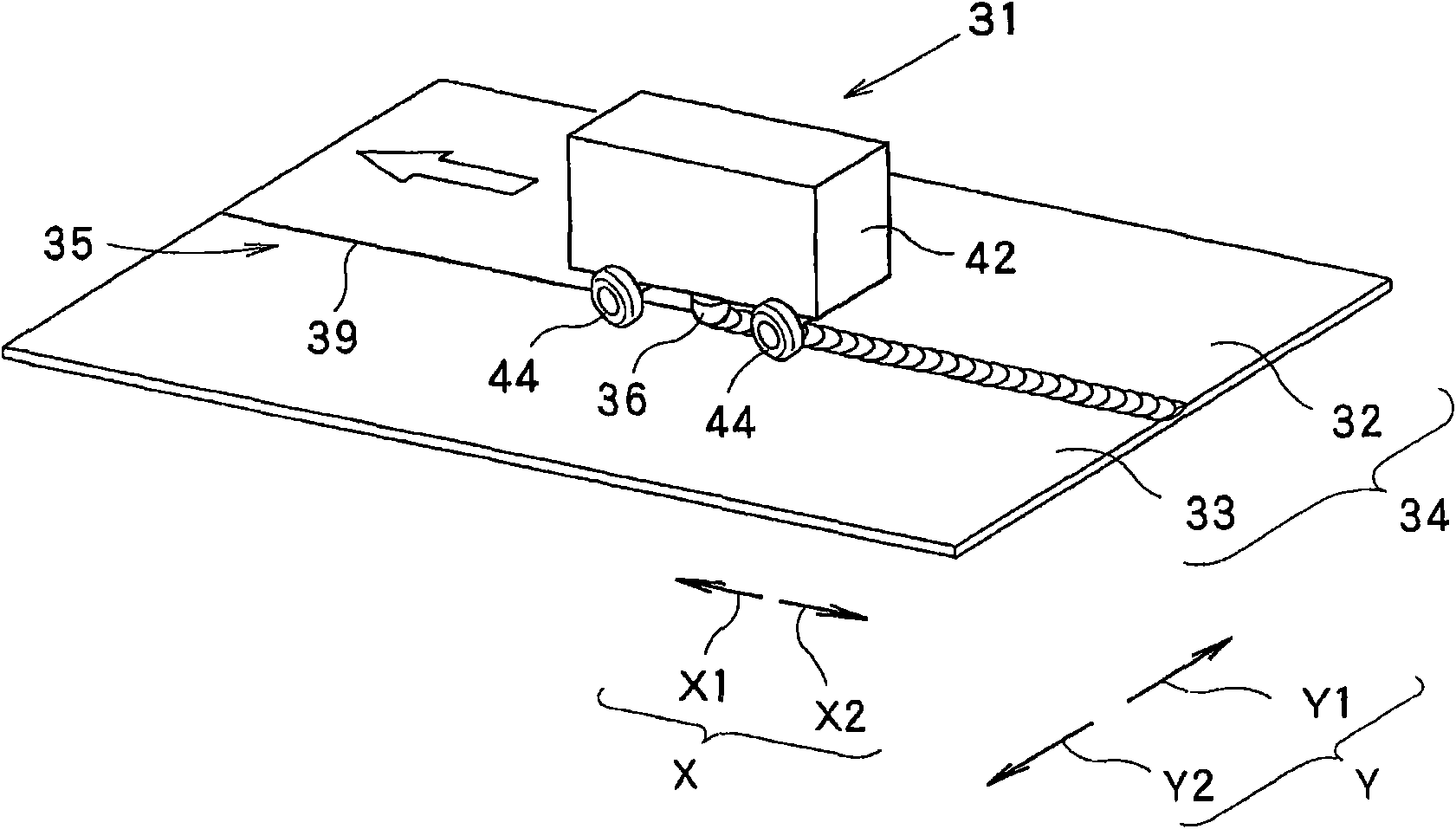
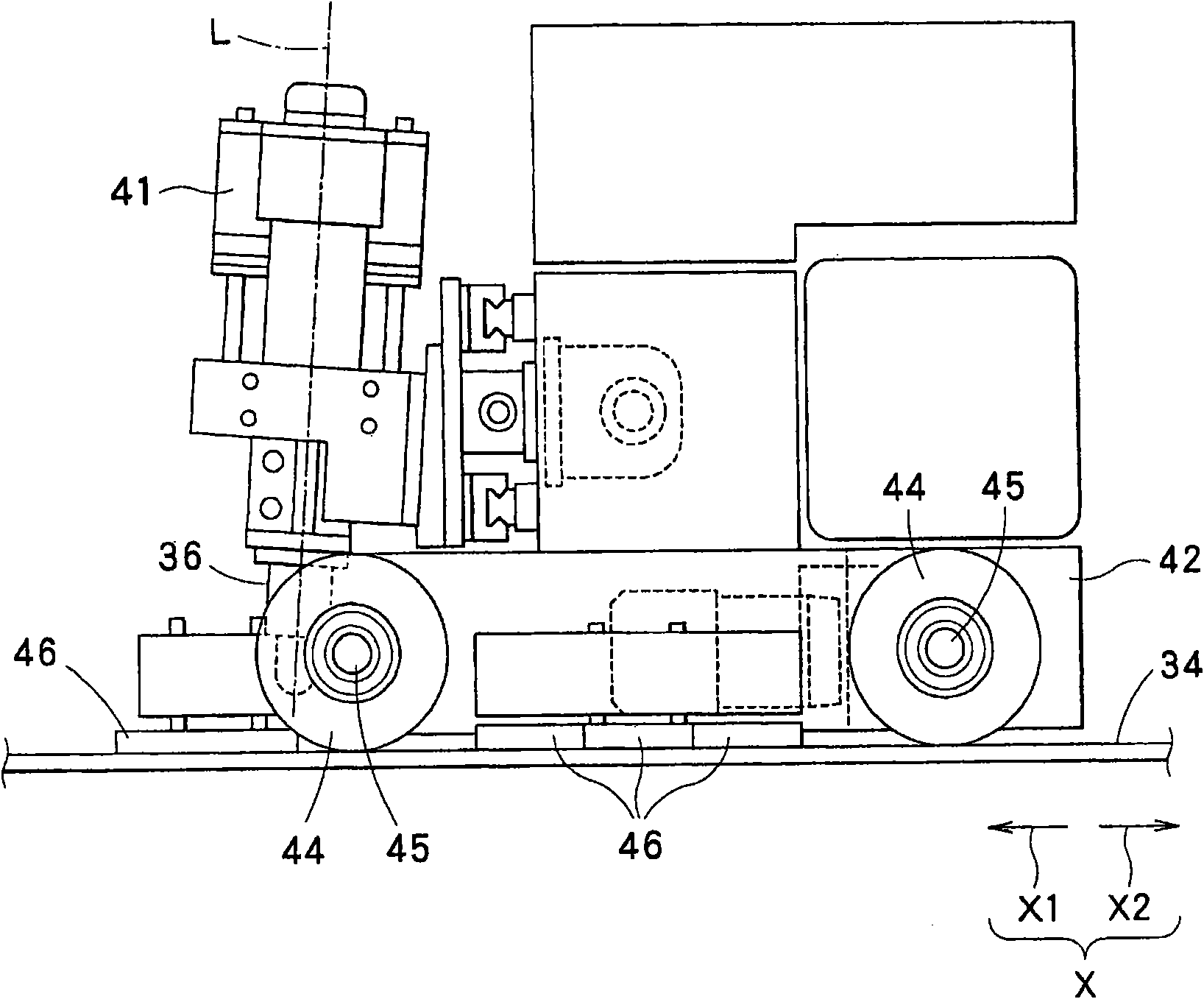
[0080] figure 1 It is a side view schematically showing a friction stir welding device (hereinafter, simply referred to as a welding device 31 ) according to an embodiment of the present invention. figure 2 It is a perspective view showing the running state of the joining device 31 .

[0081] The joining device 31 joins a to-be-joined object 34 for butting two to-be-joined objects 32 and 33 . On the object to be joined 34 , a seam portion 35 is formed at a joining site where the two objects to be joined 32 and 33 are butted together. The bonding device 31 moves the bonding tool 36 along the seam portion 35 to continuously bond the objects 32 and 33 to be bonded. The seam portion 35 has a joint line 39 as a boundary line of the respective objects 32 , 33 to be joined formed on the surface. The bonding wire 39 extends linearly in this embodiment.

[0082] A cylindrical bonding tool 36 is attached to the bonding device 31 , and friction stir welding is performed using the b...


PUM


Abstract

Provided are a friction sir welding device that is light in weight and can travel by a small force, a suction pad used for the friction sir welding device, and a friction stir welding system. The suction pad (46) includes a plate-like facing section (51) facing an object to which the suction pad sticks; an annular pad section (52) projecting from one surface in the thickness direction of the facing section (51) at its end near the object and making a round on the surface of the facing section (51); a gliding body (53) provided on the surface of the pad section (52) at a portion near the object; and one or more deformation prevention projections (56) projecting from the one surface in the thickness direction of the facing section (51). The gliding body (53) is made of a material having a friction coefficient against the object which is smaller than the friction coefficient of the pad section (52) against the object.

Description

technical field [0001] The present invention relates to a friction stir welding device that performs friction stir and joins a plurality of objects to be joined, an adsorption pad used in the friction stir welding device, and a friction stir welding system. Background technique [0002] As a method of joining a plurality of objects to be joined, there is a friction stir welding apparatus that performs friction stir welding with a joining tool. [0003] Figure 17 It is a perspective view schematically showing the table movable friction stir welding device 1 . This friction stir welding apparatus 1 includes a welding tool 2 , a table 4 on which an object to be joined 3 is placed, and a moving table 5 that moves the table 4 in one direction. The workbench 4 and the object 3 placed on the workbench 4 are along the Figure 17 Move in the walking direction indicated by arrow 6. The bonding tool 2 can be displaced in the direction of approaching or moving away from the table 4, ...

Claims


Application Information

Patent Timeline
Patent Type & Authority Applications(China)
IPC IPC(8): B23K20/12B23K20/26B23K37/02
CPCB23K20/1245B23K2201/18F16B47/00B23K2203/10B23K37/0294B23K2101/18B23K2103/10B23K20/12B23K20/26B23K37/02
Inventor 藤本光生西田英人
Owner KAWASAKI JUKOGYO KK
Learn More