
Electroplating apparatus

An electroplating device and electrode technology, applied in the electrolysis process, electrolysis components, etc., can solve the problems of reduced operating efficiency, electroplating adhesion, uneven thickness of electroplating film, and damage to the inner peripheral surface of the cylinder, so as to improve operating efficiency and prevent being damaged damage effect

Inactive Publication Date: 2010-01-06
SUZUKI MOTOR CO LTD
View PDF3 Cites 3 Cited by
  • Summary
  • Abstract
  • Description
  • Claims
  • Application Information

AI Technical Summary

Problems solved by technology

[0005] However, when using the plating apparatus in which the electrodes are fixed as disclosed in Patent Document 1, the cylinder inner peripheral surface and the electrodes may come into contact with each other in attaching or detaching the cylinder block, thereby damaging the cylinder inner peripheral surface.
In particular, damage to the inner peripheral surface of the cylinder after the pre-plating process can cause defects such as plating adhesion and uneven plating film thickness
Therefore, the operator needs to carefully attach and detach the cylinder block, which leads to a decrease in operating efficiency

Method used


Image

  • Electroplating apparatus
  • Electroplating apparatus
  • Electroplating apparatus

Examples


no. 1 example

[0033] [The first embodiment ( Figure 1 to Figure 1 0)]

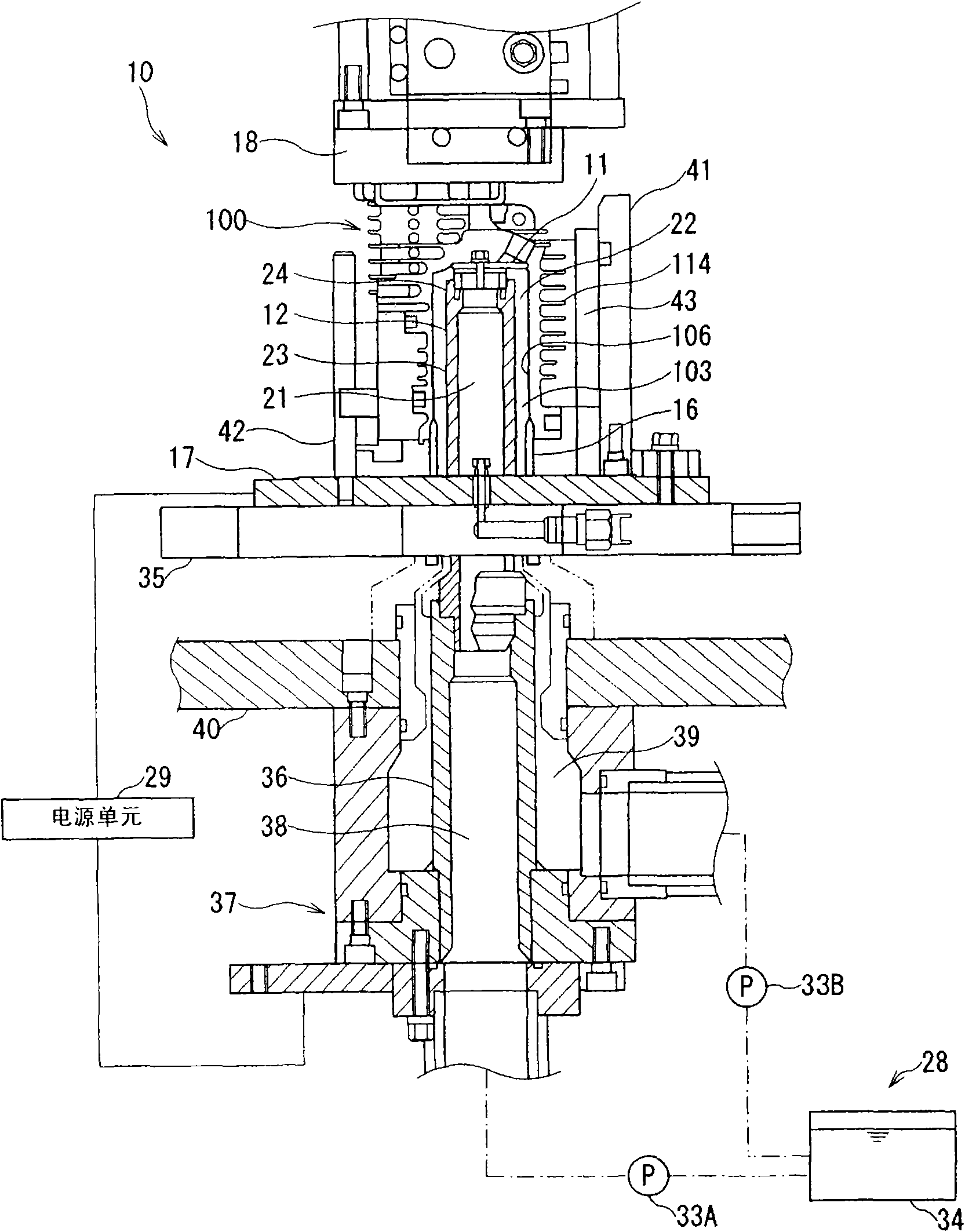
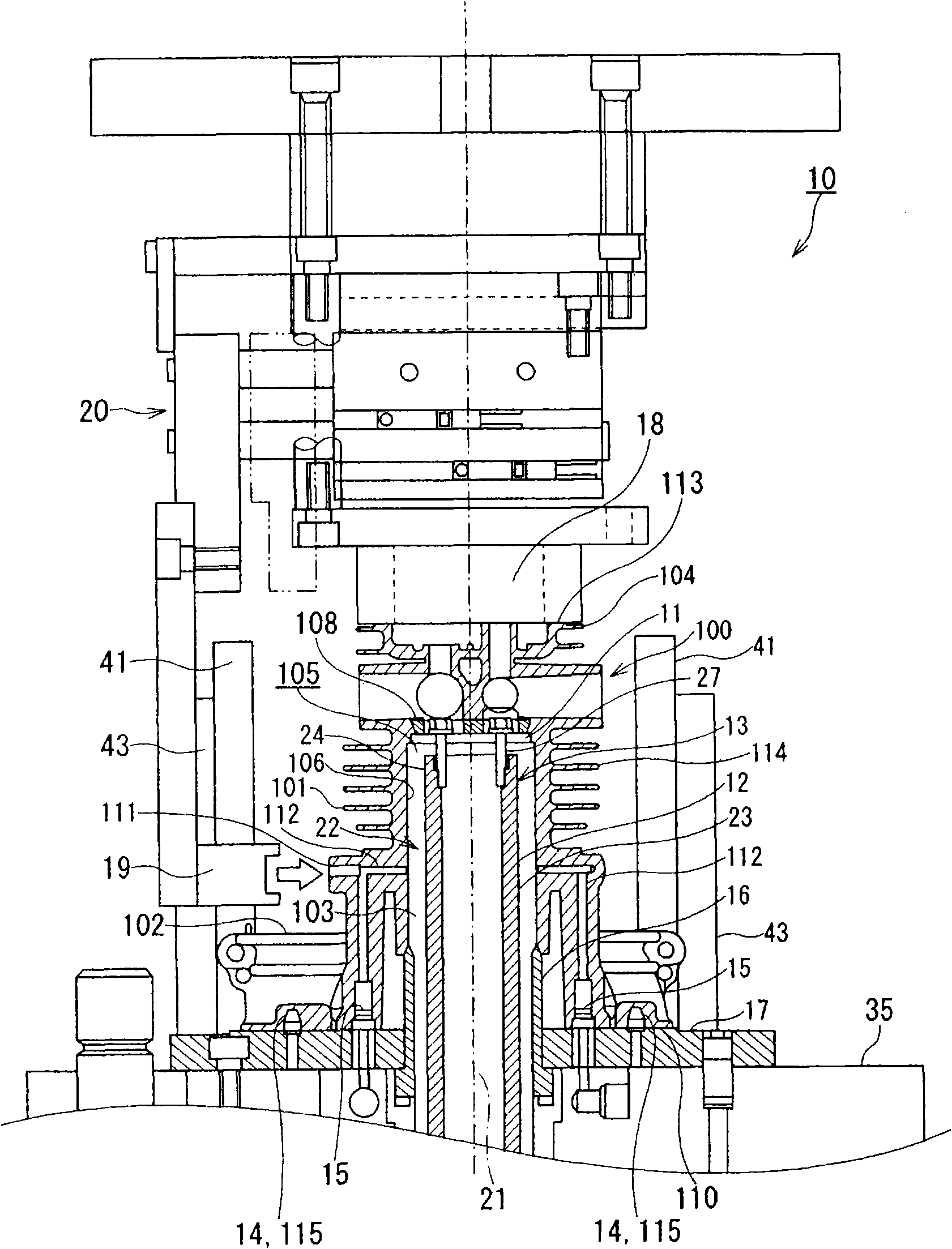
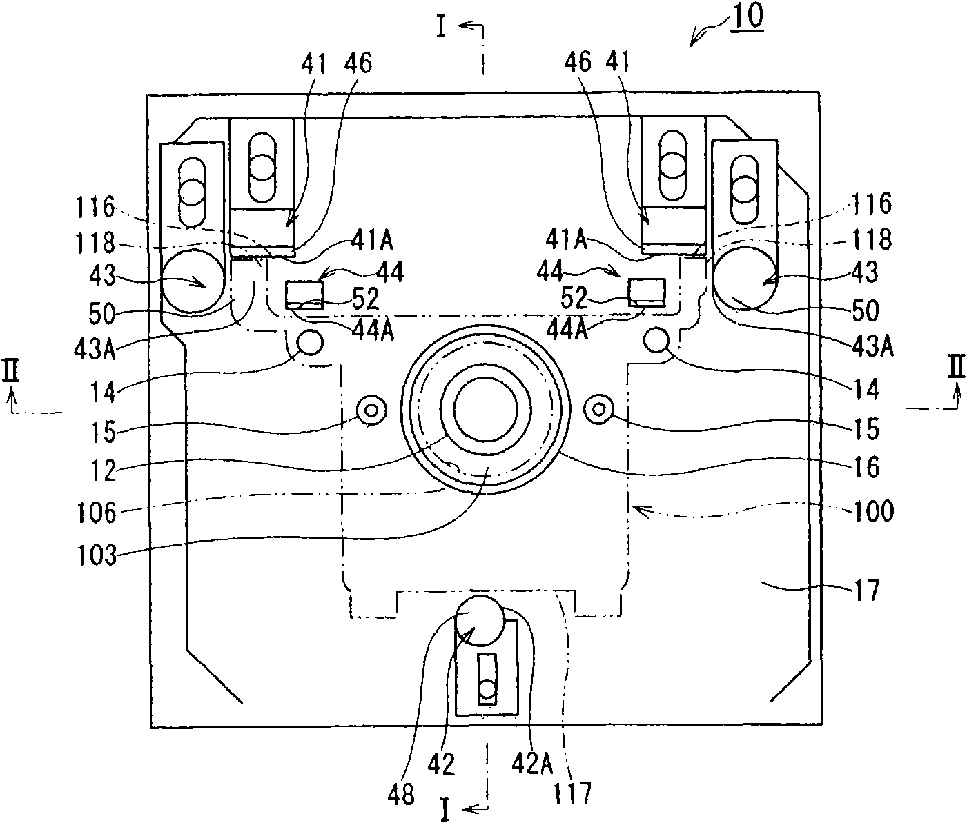
[0034] Figure 1 to Figure 3 The illustrated plating device 10 functions to forcibly introduce and flow a treatment solution (pre-plating solution or plating solution) to the cylinder inner peripheral surface 106 of the cylinder block 100 of the engine so that the cylindrical electrode 12 and the cylinder block 100 are energized A pre-plating process or a plating process is performed on the cylinder inner peripheral surface 106 at high speed.

[0035] For the above purpose, the electroplating apparatus 10 includes: an electrode unit 13 including a cylindrical electrode 12 and a first sealing member 11; a workpiece mounting platform 17 including a positioning pin 14; a connector pin 15 as a connecting member and a second sealing member 16 a work holding fixture (work holding fixture) 18; a closing unit 20 comprising a third sealing member 19; a processing liquid supply unit 28; a power supply unit 29; including an ins...

no. 2 example

[0102] [The second embodiment ( Figure 11 )]

[0103] Figure 11 With Figure 8 Correspondingly, a schematic side view of the main part of the second embodiment of the electroplating apparatus according to the present invention is shown. In the second embodiment, parts similar to those of the first embodiment are identified by the same reference numerals, and descriptions thereof are simplified or omitted.

[0104] The electroplating apparatus 60 of the second embodiment is different from the electroplating apparatus 10 in the first embodiment in that the insertion guide 61 includes a prism portion 62, a cylindrical portion 63 integrally provided at the top end of the prism portion 62, and a tapered portion 64. and 65 , tapered portions 64 and 65 tapered toward their respective pointed ends, are formed on the top ends of the prismatic portion 62 and the cylindrical portion 63, respectively.

[0105] The taper angle of the tapered portion 64 at the top end of the prism por...


PUM


Abstract

An electroplating apparatus for pre-electroplating or electroplating the inner circumference surface of an air cylinder. In the electroplating apparatus, plane parts are formed on the external wall of the cylinder block on a crankshaft case side of an engine and opposite with each other, a shaft is vertical to the crankshaft case surface and parallel to a cylinder chamber, electrodes are projected from a workpiece mounting platform which contact with the crankshaft case surface of the cylinder block thereon, and a workpiece guide member including an insertion guide piece and an auxiliary guide piece is configured to parallel to a cylindrical electrode on a position of the insertion guide part and the auxiliary guide part facing to the plane parts and stands on the workpiece mounting platform vertically, wherein the insertion guide piece and the auxiliary guide piece are provided with sliding surfaces where the plane parts slide.

Description

technical field [0001] The present invention relates to a plating apparatus for efficiently pre-plating or electroplating the cylinder inner peripheral surface of a cylinder block in an engine, for example, in which electrodes are opposed to the cylinder inner peripheral surface. Background technique [0002] Japanese Patent Laid-Open No. 2001-193550 (Patent Document 1) discloses an electroplating apparatus that performs an electroplating process while a treatment liquid flows on a cylinder inner peripheral surface of a cylinder block. The plating apparatus flows the treatment liquid toward the inner peripheral surface of the cylinder as the surface to be treated, and in this case, performs a pre-plating or electroplating process or treatment. Such a plating apparatus has an advantage that a pre-plating or electroplating process can be performed regardless of the size of the cylinder block. [0003] In addition, the plating apparatus can be easily installed on a production ...

Claims


Application Information

Patent Timeline
IPC IPC(8): C25D5/08C25D17/00
Inventor 须田尚幸国冈诚也村松仁铃木伸行麻生智广河合真石桥亮
Owner SUZUKI MOTOR CO LTD
Learn More