Eureka AIR delivers breakthrough ideas for toughest innovation challenges, trusted by R&D personnel around the world.

High-efficiency film coating machine for solar thermal-collecting tubes

A solar collector tube, coating machine technology, applied in sputtering coating, ion implantation coating, vacuum evaporation coating and other directions, can solve the problems of low space utilization rate of vacuum chamber, low equipment capacity, etc., to reduce production costs and Low energy consumption cost, small equipment cost, small increase effect

Inactive Publication Date: 2010-01-06
ZHEJIANG UNIV OF TECH
View PDF0 Cites 11 Cited by
  • Summary
  • Abstract
  • Description
  • Claims
  • Application Information

AI Technical Summary

Problems solved by technology

[0008] In order to overcome the low utilization rate of the vacuum chamber space of the existing solar heat collector tube coating machine, which leads to the low production capacity of the equipment, the present invention provides a high-efficiency vacuum chamber space utilization rate that can effectively improve the equipment production capacity and reduce energy consumption. Solar collector tube coating machine

Method used

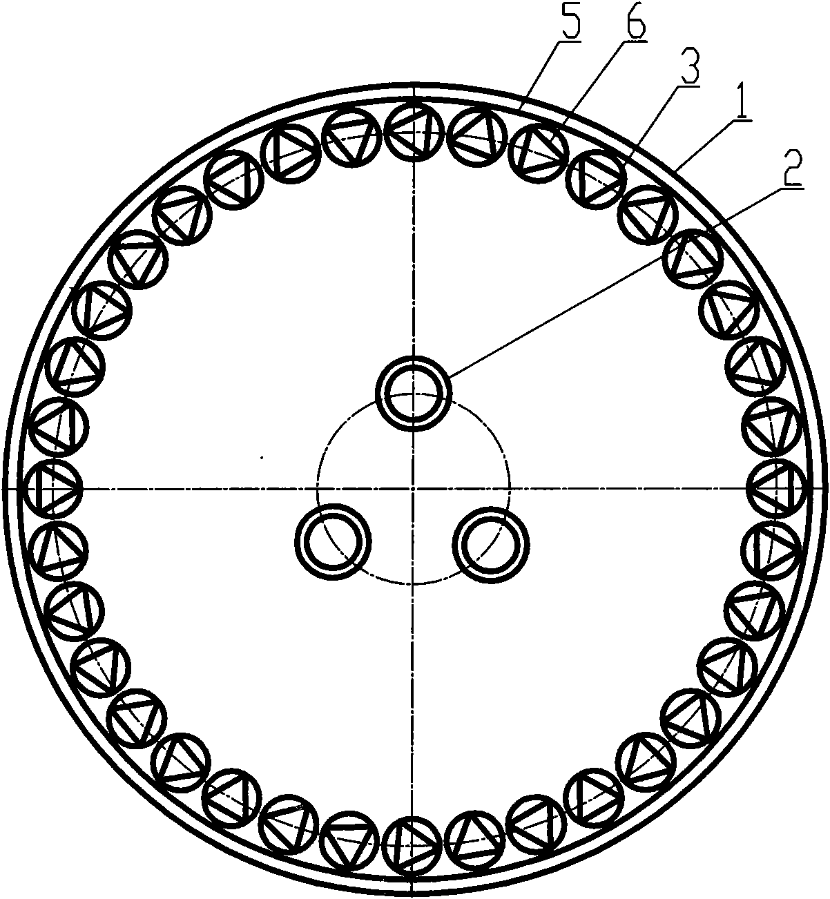
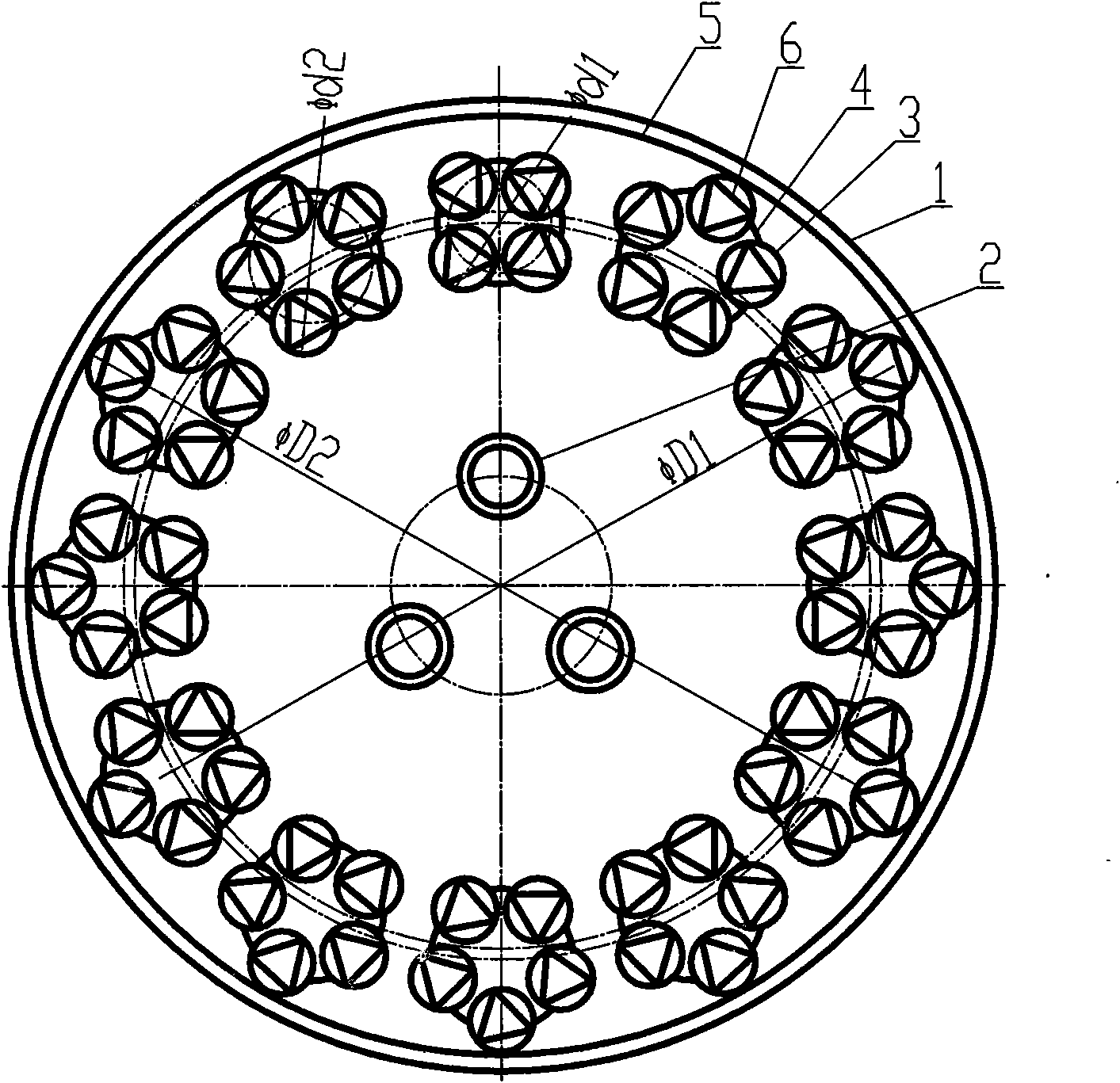
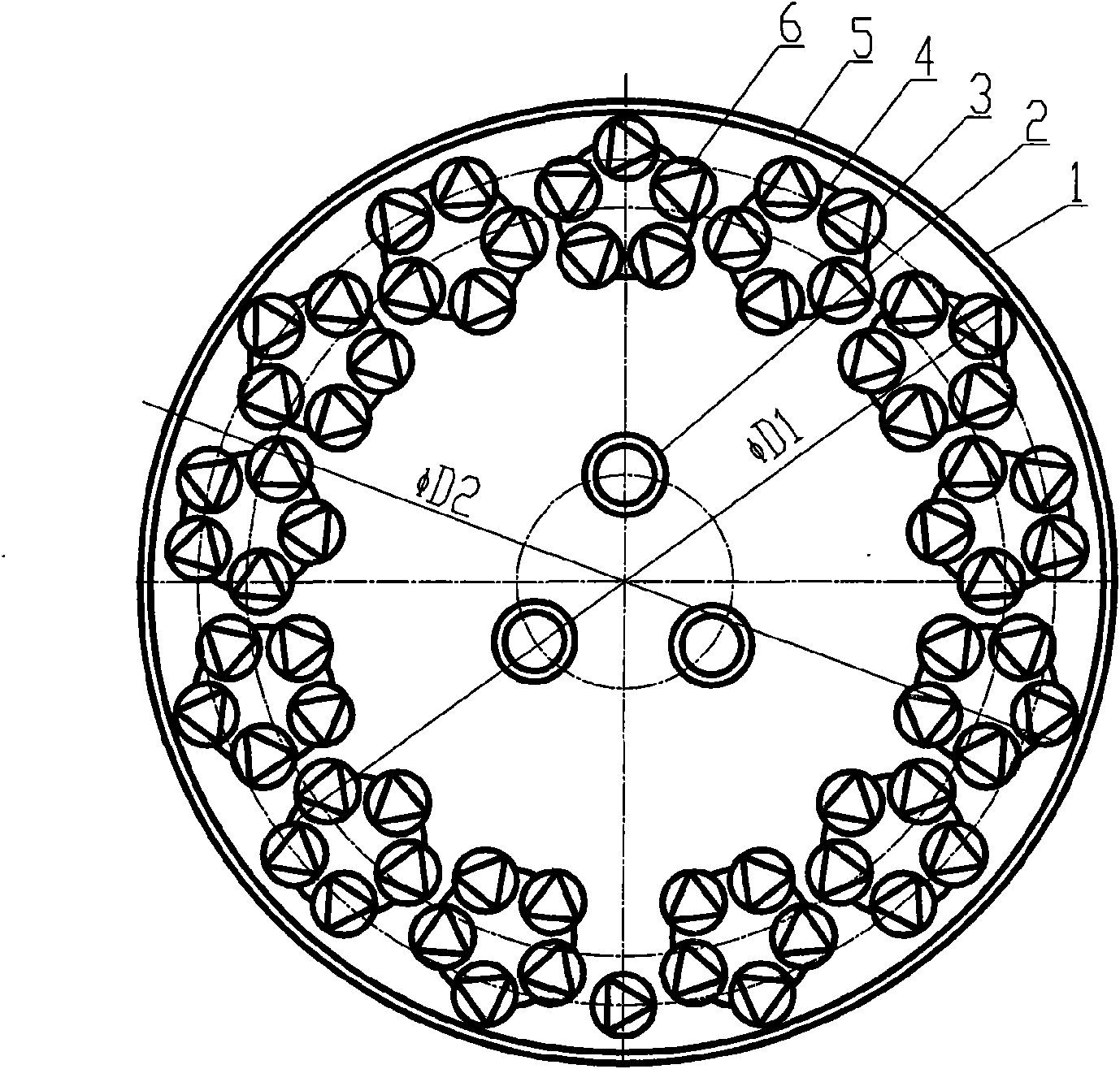

Image

  • High-efficiency film coating machine for solar thermal-collecting tubes
  • High-efficiency film coating machine for solar thermal-collecting tubes
  • High-efficiency film coating machine for solar thermal-collecting tubes

Examples


Embodiment 1

[0032] refer to figure 2 , a high-efficiency solar collector tube coating machine, including a vacuum chamber 1, a target 2, a turntable 5 and a clamp 6, the vacuum chamber 1 is a cylindrical cylinder, the cylindrical cylinder has a door, and the target The pole 2 is a cylindrical elongated part that rotates around its axis, the target pole 2 is located in the center of the turntable 5, the turntable 5 is located in the vacuum chamber 1, and the solar heat collector workpiece 3 is clamped on the fixture 6 , the clamp 6 is connected with the driving device through the rotation motion transmission chain, and the turntable 5 is connected with the driving device through the revolution motion transmission chain, and the high-efficiency solar collector tube coating machine also includes 12 turntables 4; all the clamps 6 are installed On the turntable 4; there are two arrangement modes of n=5 clamps 6 and n=4 clamps 6 on the turntable 4; The revolution transmission chain is connect...

Embodiment 2

[0038] refer to image 3 , a high-efficiency solar collector tube coating machine, including a vacuum chamber 1, a target 2, a turntable 5 and a clamp 6, the vacuum chamber 1 is a cylindrical cylinder, the cylindrical cylinder has a door, and the target The pole 2 is a cylindrical elongated part that rotates around its axis, the target pole 2 is located in the center of the turntable 5, the turntable 5 is located in the vacuum chamber 1, and the solar heat collector workpiece 3 is clamped on the fixture 6 , the clamp 6 is connected with the driving device through the rotation motion transmission chain, and the turntable 5 is connected with the driving device through the revolution motion transmission chain, and the high-efficiency solar collector tube coating machine also includes 13 turntables 4; 65 clamps 6 Installed on the turntable 4, a fixture 6 is directly installed on the turntable 5; n=5 fixtures are arranged on each turnframe 4; the turnframe 4 is installed on the tur...

Embodiment 3

[0044] refer to Figure 4 , a high-efficiency solar collector tube coating machine, including a vacuum chamber 1, a target 2, a turntable 5 and a clamp 6, the vacuum chamber 1 is a cylindrical cylinder, the cylindrical cylinder has a door, and the target The pole 2 is a cylindrical elongated part that rotates around its axis, the target pole 2 is located in the center of the turntable 5, the turntable 5 is located in the vacuum chamber 1, and the solar heat collector workpiece 3 is clamped on the fixture 6 , the clamp 6 is connected with the driving device through the rotation motion transmission chain, and the turntable 5 is connected with the driving device through the revolution motion transmission chain, and the high-efficiency solar collector tube coating machine also includes 12 turntables 4; all the clamps 6 are installed On the turntable 4; there are n=5 clamps 6 on each turnframe 4; the turntable 4 is installed on the turntable 5; the turntable 4 is connected with the...


PUM


Abstract

The invention relates to a high-efficiency film coating machine for solar thermal-collecting tubes, which comprises a vacuum chamber, a target, a turntable and clamps, wherein the vacuum chamber is a cylinder body provided with a door; the target is a cylindrical lathy component which rotates around an axis of the cylinder body; and the target is arranged in the center of the turntable arranged in the vacuum chamber. Workpiece sheaths of solar thermal-collecting tubes are clamped on the clamps which connected with a driving device by an autorotation transmission chain, and the turntable is connected with the driving device by a revolution transmission chain. The high-efficiency film coating machine for the solar thermal-collecting tubes also comprises more than two rotating stands provided with clamps with the number of n. The rotating stands are installed on the turntable, and are connected with the driving device by an additional revolution transmission chain. The rotating center of each clamp on each rotating stand is arranged in a circle gridle using the rotating center of the rotating sand as the center of a circle; and the rotating center of each rotating stand is arranged in a circle gridle using the rotating center of the turntable as the center of a circle. The high-efficiency film coating machine for the solar thermal-collecting tubes can effectively enhance the energy production capability of equipment, and reduce the production cost and the energy consumption cost for the film coating of the thermal-collecting tubes.

Description

technical field [0001] The invention relates to a coating machine for solar heat collecting tubes. Background technique [0002] In recent years, solar thermal utilization technologies such as solar water heaters and solar air-conditioning systems are occupying most of the world's renewable energy utilization fields with an unprecedented development trend. Among them, the all-glass solar vacuum heat collector becomes the core component of the solar heat utilization equipment. The key equipment for the production of all-glass solar vacuum heat collector tubes is the solar heat collector tube vacuum coating machine, especially the magnetron sputtering vacuum coating machine. The vacuum chamber adopts a vertical cylindrical cylinder with a front door. (that is, glass blank tubes) are evenly arranged at equal intervals in the cylinder on a circle concentric with the center of rotation of the turntable in the cylinder. In order to accommodate as many workpieces as possible, the ...

Claims


Application Information

Patent Timeline
IPC IPC(8): C23C14/34
Inventor 谢伟东
Owner ZHEJIANG UNIV OF TECH
Why Eureka
Eureka Blog
Learn More