
Electronic component and manufacture method thereof

A technology of electronic components and manufacturing methods, applied in semiconductor/solid-state device manufacturing, electrical components, circuits, etc.

Active Publication Date: 2011-09-28
MURATA MFG CO LTD
View PDF1 Cites 0 Cited by
  • Summary
  • Abstract
  • Description
  • Claims
  • Application Information

AI Technical Summary

Problems solved by technology

As a result, in appearance sorting, even if there is no exposure defect, it may be misjudged that the electrode pattern for coil formation is exposed in the bright part.

Method used


Image

  • Electronic component and manufacture method thereof
  • Electronic component and manufacture method thereof
  • Electronic component and manufacture method thereof

Examples


Embodiment Construction

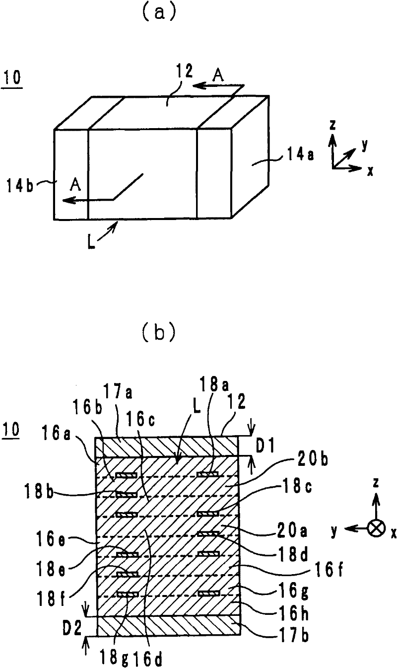
[0020] An electronic component and its manufacturing method according to one embodiment of the present invention will be described below.

[0021] (composition of electronic components)

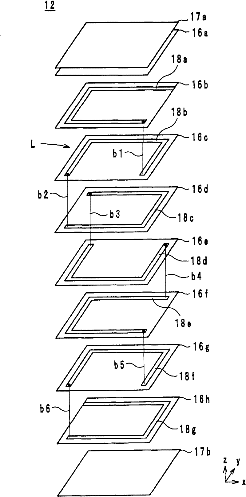
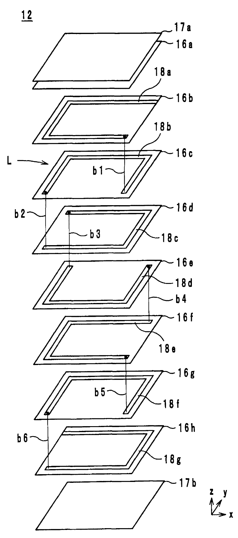
[0022] figure 1 (a) is a perspective view of the appearance of the electronic assembly 10; figure 1 (b) is an A-A sectional structural diagram of the electronic module 10 . figure 2 It is an exploded perspective view of the laminated body 12 of the electronic module 10 . Hereinafter, the stacking direction of the electronic component 10 is defined as the z-axis direction; the direction along the long side of the electronic component 10 is defined as the x-axis direction; and the direction along the short side of the electronic component 10 is defined as the y-axis direction. exist figure 1 In (b), the boundary line of each layer is shown by the dotted line, but in reality, there may be no recognizable boundary line.

[0023] like figure 1 As shown in (a), the electronic component 10 in...


PUM

PropertyMeasurementUnit
thicknessaaaaaaaaaa
particle diameteraaaaaaaaaa
thicknessaaaaaaaaaa

Abstract

The invention provides an electronic component that is not easy to expose a bad misjudge, and a manufacture method thereof. A plurality of magnetic body layers (16, 17) are laminated to form a laminated body (12). A plurality of coil electrodes (18) and the magnetic body layer (16) are laminated to form a coil L. In direction of Z axis of the laminated body (12), a scope of at least 5 Mum from a face of two ends is formed by a porous insulating layer (17) with the void ratio of 3.0%-35.0%.

Description

technical field [0001] The present invention relates to an electronic component and a manufacturing method thereof, in particular to an electronic component in which a coil is housed in a laminated body and a manufacturing method thereof. Background technique [0002] As a conventional electronic component, for example, a multilayer inductor described in Patent Document 1 is known. In this multilayer inductor, multilayer insulating layers and a plurality of conductive patterns for coil formation are alternately laminated; a plurality of conductive patterns for coil formation are connected to each other to form a coil; they are arranged on the uppermost side and the lowermost side of the stacking direction. The conductive pattern for coil formation is drawn out on the side surface of the laminated body made of the insulating layer, and connected to the external electrode on the side surface of the laminated body. [0003] In the multilayer inductor configured as above, appea...

Claims


Application Information

Patent Timeline
Patent Type & Authority Patents(China)
IPC IPC(8): H01F37/00H01L21/02
Inventor 黑部淳司河野大司
Owner MURATA MFG CO LTD
Learn More