
Displacement and velocity sensor

A speed sensor and displacement technology, which is applied in the direction of instruments, measuring devices, devices using optical methods, etc., can solve problems such as difficult correction and function expansion, difficult manufacturing process, poor environmental adaptability, etc., and achieve easy function expansion, material Large selection range and low cost effects

Active Publication Date: 2009-12-30
长春长光启衡传感技术有限公司
View PDF0 Cites 6 Cited by
  • Summary
  • Abstract
  • Description
  • Claims
  • Application Information

AI Technical Summary

Problems solved by technology

The manufacturing process is difficult, the environment adaptability is poor, and it is not easy to correct and expand functions

Method used


Image

  • Displacement and velocity sensor
  • Displacement and velocity sensor
  • Displacement and velocity sensor

Examples


Embodiment 1

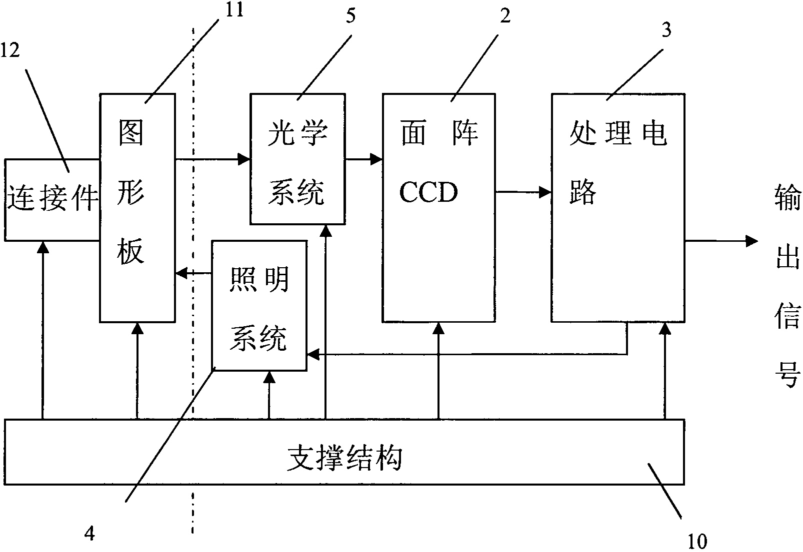
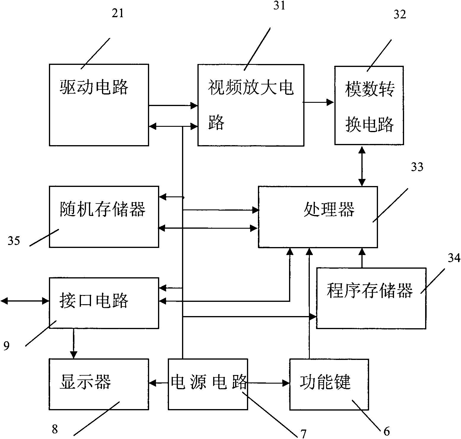
[0021] like figure 2 As shown, the area array detector 2 adopts an area array CCD, and the image signal source 1 is a graphics board 11 with a graphic logo, and the graphics board 11 is connected to the object to be measured through a connecting piece 12 . The light emitted by the lighting system 4 is irradiated on the graphics board 11, and the graphics board 11 is imaged on the area array CCD through the optical system 5, and the area array CCD converts the image signal of the graphics board 11 into an electrical signal and transmits it to the processing circuit 3, and the processing circuit 3 Calculate and output the displacement and velocity of the object to be measured according to the image position information of the graphic mark. The entire device is built on a support structure 10 .

[0022] The lighting system 4 can adopt LED light sources or other common light sources.

[0023] The optical system 5 may adopt a condenser lens or other optical elements capable of m...

Embodiment 2

[0036] like Figure 7 As shown, the area array detector 2 adopts an area array CCD, and the image signal source 1 is a graphic mark 14 fixed on the object to be measured. The graphic mark 14 can adopt the same or different figure as that in Embodiment 1. The light emitted by the lighting system 4 is irradiated on the object 13 to be measured, and the object 13 to be measured and the graphic mark 14 are imaged on the area array CCD through the optical system 5, and the area array CCD converts the image signal of the object 13 to be measured into an electrical signal and transmits it to the The processing circuit 3 calculates and outputs the angular displacement and velocity of the object to be measured according to the image position information of the graphic mark 14 on the object to be measured 13 . The entire device is built on a support structure 10 .

[0037] The lighting system 4 can adopt LED light sources or other common light sources.

[0038] The optical system 5 ma...


PUM


Abstract

The invention relates to a displacement and velocity sensor. The sensor comprises an image signal source, a flat-panel detector and a processing circuit; the flat-panel detector carries out imaging on the image signal source, converts image signals into electrical signals and then transmits to the processing circuit; and the processing circuit calculates and processes received electrical signals, and outputs signals indicating the displacement and velocity physical quantities of objects to be detected. By adopting the invention, the measurement values of displacement and velocity with higher accuracy can be obtained easily; the sensor can be installed and debugged with an object to be detected without the need of separately setting absolute zero information, then absolute zero is set, after installation and utilization, the sensor can be easily adjusted, even disposal methods can be changed, thus the sensor is convenient for installation and debugging, and easy for correction and function expansion.

Description

technical field [0001] The invention relates to a displacement and velocity sensor, in particular to a displacement and velocity sensor which uses an area array detector to convert the displacement and velocity information of an object to be measured into electrical signals. Background technique [0002] Traditional displacement and speed sensors design various complex code tracks on the code disc as the criterion of displacement; use semiconductor photoelectric light-emitting and receiving devices to collect local code track information of the code disc, and use the processing circuit to analyze the collected information. Perform calculation and processing and output signals representing the physical quantities of displacement and velocity of the object to be measured. To achieve high-precision displacement, the design of the code track is required to be exquisite, the processing precision is high, and the assembly and adjustment are complicated. Its function and accuracy m...

Claims


Application Information

Patent Timeline
IPC IPC(8): G01B11/02G01P3/38
Inventor 贾平
Owner 长春长光启衡传感技术有限公司
Learn More