Centrifugal compressor case

A centrifugal compressor and compressor technology, applied in the field of compressors, can solve the problems of changing the sealing gap, energy loss, and the efficiency of centrifugal compressor units.

Active Publication Date: 2009-12-30
SHANGHAI JIAO TONG UNIV
View PDF3 Cites 9 Cited by
  • Summary
  • Abstract
  • Description
  • Claims
  • Application Information

AI Technical Summary

Problems solved by technology

The disadvantage of these inventions is that the slotting changes the sealing gap between the impeller and the casing, which will cause energy loss in the entire operating range, resulting in a decrease in the efficiency of the centrifugal compressor unit

Method used


Image

  • Centrifugal compressor case
  • Centrifugal compressor case

Examples


Embodiment Construction

[0017] The embodiments of the present invention are described in detail below. This embodiment is implemented on the premise of the technical solution of the present invention, and detailed implementation methods and specific operating procedures are provided, but the protection scope of the present invention is not limited to the following implementation example.

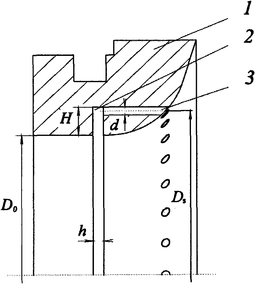
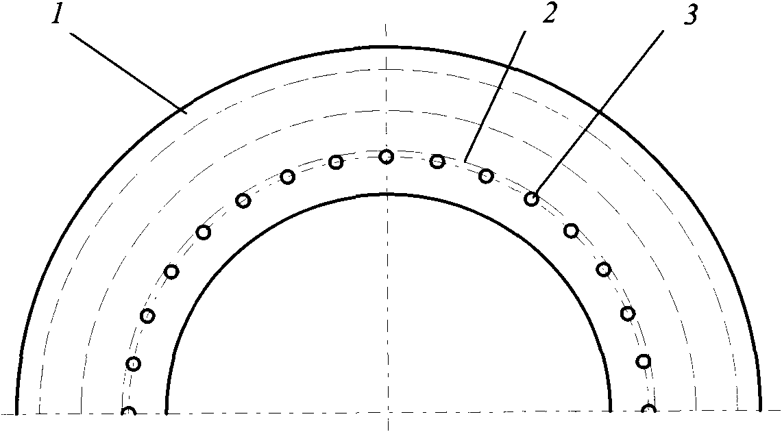
[0018] Such as figure 1 and figure 2 As shown, the compressor casing 1 in this embodiment is an annular structure, including: an annular gas collection groove 2 and a through hole 3, wherein: the through hole 3 is located on the interface between the compressor casing 1 and the impeller of the centrifugal compressor And perpendicular to the inlet annular plane of the compressor casing 1, the annular gas collection groove 2 is located in front of the inner centrifugal compressor impeller of the compressor casing 1 and is perpendicular to the axis of the through hole 3.

[0019] Such as figure 1 As shown, the ang...


PUM

PropertyMeasurementUnit
Diameteraaaaaaaaaa

Abstract

A centrifugal compressor case belongs to the field of compressor; the compressor case is provided with an annular gas collection trough and a plurality of through holes, wherein the through holes are located in the connecting surface between the compressor case and a centrifugal compressor impeller and are vertical to the inlet annular plane of the compressor case, and the annular gas collection trough is located below the internal centrifugal compressor impeller of the compressor case and is vertical to the axis of the through holes. The invention can adaptively control the regurgitant volume to enlarge the stable work area of the centrifugal compressor under the condition of not reducing the efficiency of the original machine set, thus avoiding the occurrence of surging phenomenon caused by flow instability.

Description

technical field [0001] The invention relates to a device in the technical field of compressors, in particular to a casing of a centrifugal compressor. Background technique [0002] Centrifugal compressors are widely used in the energy and power industry, and their stable operation performance determines the performance of the entire system. The main purpose of the centrifugal compressor is to increase the pressure of the gas working medium in the system. Generally, the centrifugal compressor has a certain flow range. When the flow rate drops to a certain level, the outlet pressure of the compressor increases, which will cause backflow. The occurrence of this phenomenon will cause the centrifugal compressor to surge, thereby affecting the safety and reliability of the compression system. This is a phenomenon that should be avoided as much as possible in a centrifugal compression system. [0003] After searching the prior art, it was found that the U.S. Patent Application N...

Claims


Application Information

Patent Timeline
IPC IPC(8): F04D29/42
Inventor 谷传纲王彤杨波
Owner SHANGHAI JIAO TONG UNIV
Why Eureka
Try Eureka