Lock core for electronic safe-guard door lock
An anti-theft door lock and lock cylinder technology, applied in the field of locks, can solve the problems of unstable movement, complex structure, difficult production process, etc., and achieve the effect of ensuring safety and reliability, reliable mechanism movement, and good workmanship
- Summary
- Abstract
- Description
- Claims
- Application Information
AI Technical Summary
Problems solved by technology
Method used
Image
Examples
Embodiment 1
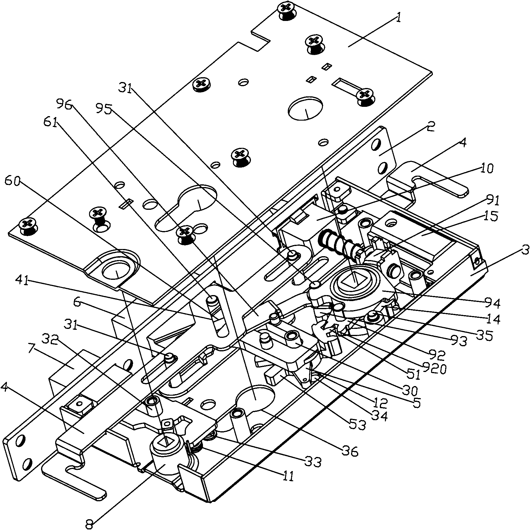
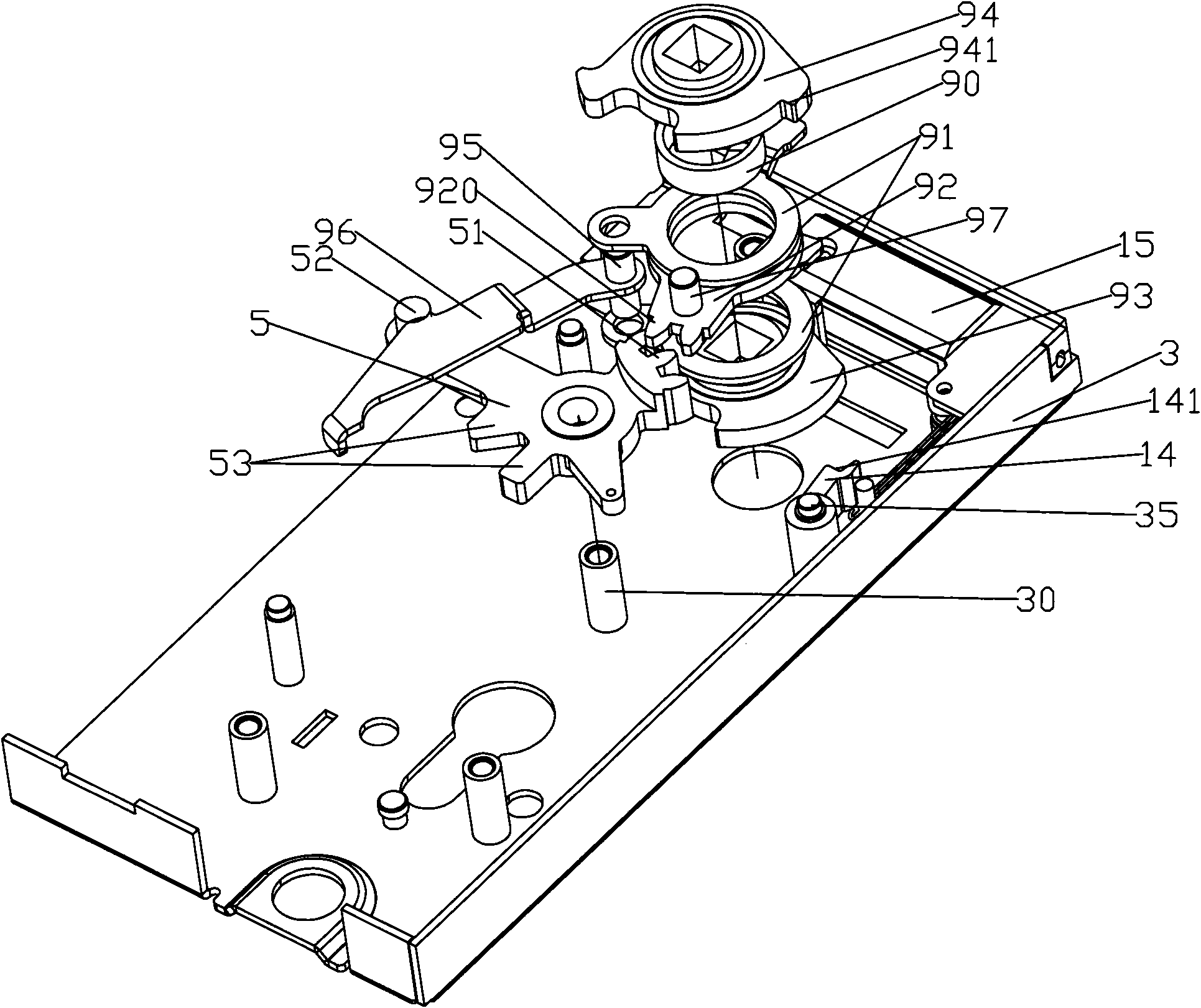
[0021] Such as figure 1 As shown, the lock core of the electronic anti-theft door lock includes a lock cover 1 and a lock case 3, the side plate 2 is fixed and installed on the lock case 3 by screws, and the sky and earth rod 4 is slidably set on the rivet post 31 in the lock case 3 , the small square tongue 7 is slidably set on the stud 32 of the lock case 3, and its front end can protrude from the small square tongue hole of the side plate 2, and the anti-lock arm 8 is rotatably set on the lock case 3, and the front end of the anti-lock arm 8 The crank arm is connected with the bayonet position provided on the small square tongue 7. Rotating the anti-lock crank arm 8 can drive the small square tongue 7 to realize anti-lock and open functions by telescopic movement in the small square tongue hole of the side plate 2. The anti-lock crank arm 8 Elastic resetting element torsion spring 11 is arranged on it, and torsion spring 11 one end is sleeved on the rivet column ` of lock h...
Embodiment 2
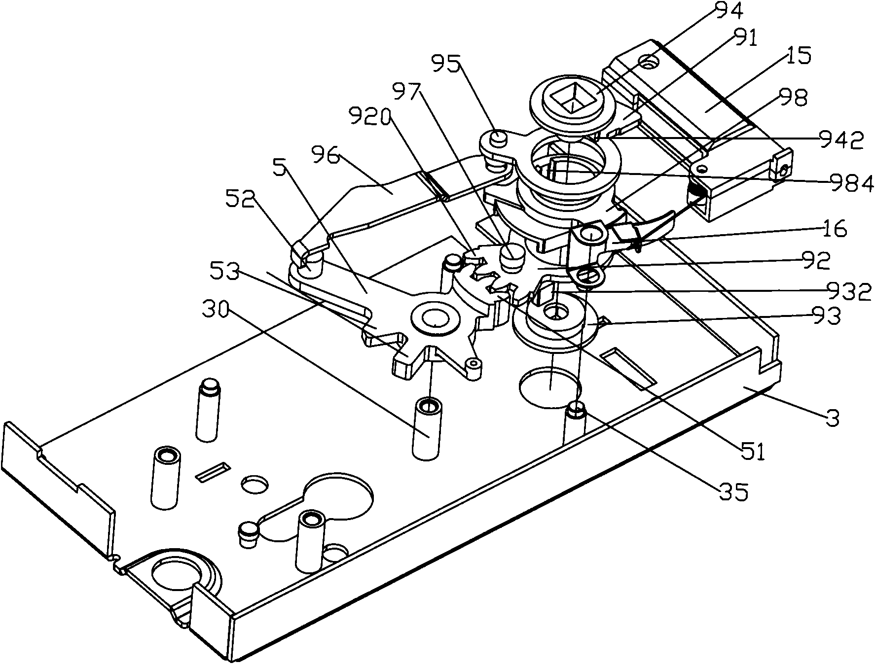
[0032] Compared with Embodiment 1, this embodiment differs in the structure of the shift fork assembly. Such as image 3 As shown, the shift fork assembly includes an idler shift fork 98, an inner shift fork 93, an outer shift fork 94, a gear plate 92, and a shifting plate 91 are coaxially and rotatably set on the idler shift fork 98, and the idler shift fork 98 An anti-rotation groove 984 is arranged on the wall of the inner hole, a rib 932 matching the anti-rotation groove 984 is arranged on the inner shift fork 93, a limit block 942 is arranged on the outer shift fork 94, and the clutch mechanism includes a clutch driven by a motor. Sheet 16, the clutch pin assembly set on the idle fork, such as Figure 4 As shown, the clutch pin assembly includes a pin hole that radially passes through the idler fork, a shift fork pin 981 arranged in the pin hole, a return spring 983 located in the pin hole and sleeved on the shift fork pin, and a pin hole at the outer end of the pin hole...
PUM
 Abstract
Description
Claims
Application Information
 - Generate Ideas
- Intellectual Property
- Life Sciences
- Materials
- Tech Scout
- Unparalleled Data Quality
- Higher Quality Content
- 60% Fewer Hallucinations
Browse by: Latest US Patents, China's latest patents, Technical Efficacy Thesaurus, Application Domain, Technology Topic, Popular Technical Reports.
© 2025 PatSnap. All rights reserved.Legal|Privacy policy|Modern Slavery Act Transparency Statement|Sitemap|About US| Contact US: help@patsnap.com


