
Reverse osmosis device for constant pressure water supply

A technology of reverse osmosis device and reverse osmosis membrane module, which is applied in osmosis/dialysis water/sewage treatment and other directions, can solve the problems of insufficiency, waste of electric energy, and inability to ensure constant water pressure, and achieve constant water supply pressure and normal water supply saving Effect

Inactive Publication Date: 2009-12-30
INST OF AUTOMATION CHINESE ACAD OF SCI +1
View PDF0 Cites 9 Cited by
  • Summary
  • Abstract
  • Description
  • Claims
  • Application Information

AI Technical Summary

Problems solved by technology

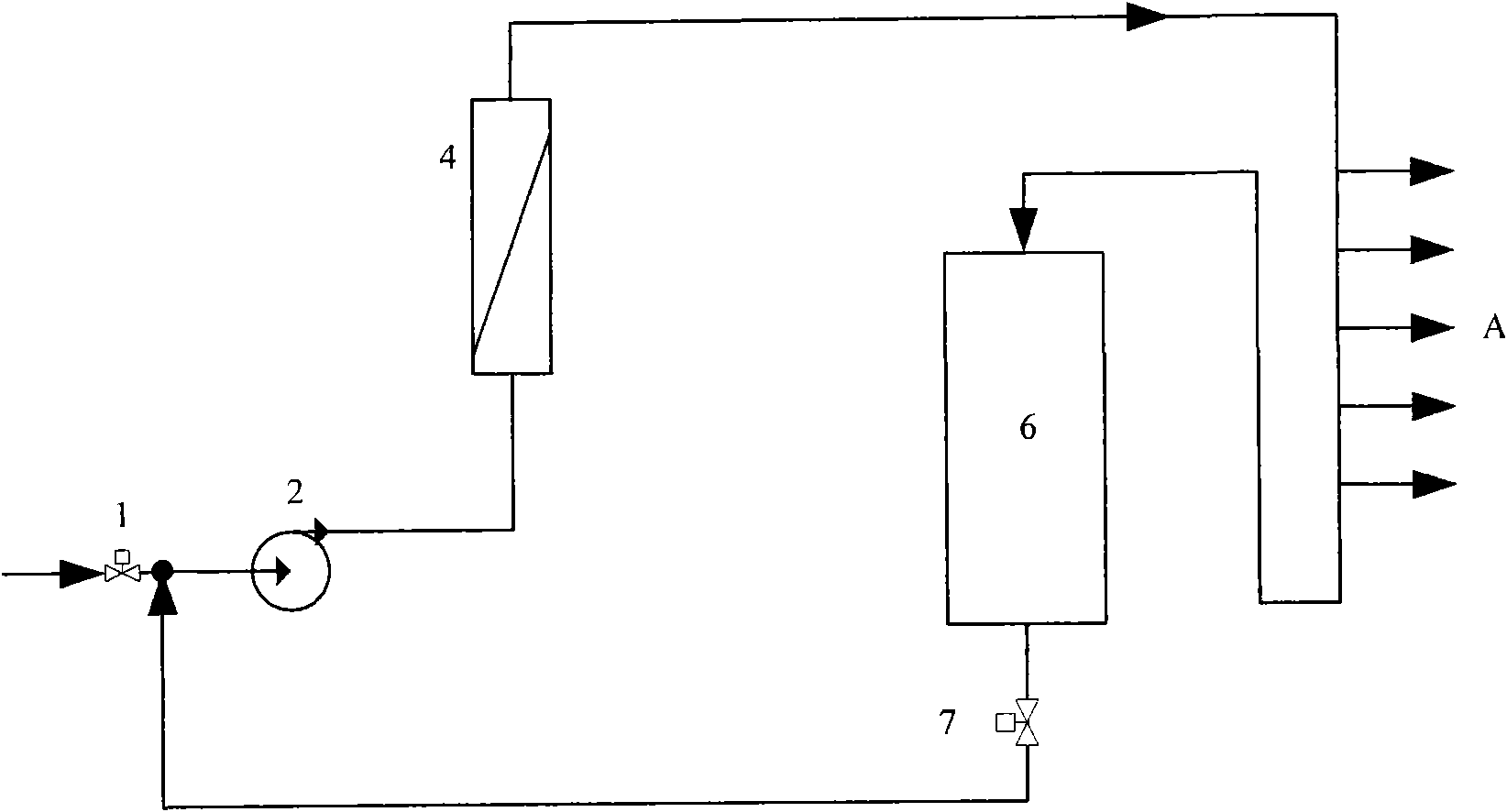
[0004] There are still some shortcomings in this reverse osmosis device: first, the device cannot guarantee the constant pressure of the produced water, because the water situation at the use point A is changing, and the water supply pressure required by the different numbers of use points A is also different, and The booster pump 2 in this device is always running at full frequency
If there are many points of use A and the pressure of the water production pipeline is insufficient, the subsequent use point A will not be able to use water, which will affect the normal use of the produced water; if there are few points of use A and the booster pump 2 is still running at full frequency, it will Cause the waste of electric energy; Secondly, the flow rate of returning to the water in the pure water tank 6 should be kept within a certain range, and the flow rate of returning water should not be too small, so as to ensure that each use point A can use water normally, and this device cannot meet this requirement. Require

Method used


Image

  • Reverse osmosis device for constant pressure water supply
  • Reverse osmosis device for constant pressure water supply

Examples


Embodiment Construction

[0015] Such as figure 2 Shown is a structural schematic diagram of a constant pressure water supply reverse osmosis device of the present invention, in the figure: water supply valve 1; booster pump 2; frequency converter 3; reverse osmosis membrane assembly 4; electric control valve 5; pure water tank 6 ; Water tank outlet solenoid valve 7; Pressure transmitter 8; Flow meter 9; Use point A.

[0016] Wherein, a frequency converter 3 is connected in parallel on the booster pump 2; an electric regulating valve 5 is arranged in the pipeline from the point of use A to the inlet of the pure water tank 6, and a flow meter 9 is arranged downstream of the electric regulating valve 5; A pressure transmitter 8 is arranged in the pipeline from the membrane module 4 to the use point A. The pressure transmitter 8 is electrically connected with the frequency converter 3 . The flowmeter 9 is electrically connected with the electric regulating valve 5 .

[0017] The pressure transmitter 8...


PUM


Abstract

The invention provides a reverse osmosis device for constant pressure water supply, and relates to constant pressure water supply technology. The reverse osmosis device comprises a water supply valve, a booster pump, a reverse osmosis membrane module, pure water tanks, a water tank outlet solenoid valve, a using point, a frequency converter, a motorized valve, a pressure transmitter and a flow meter, wherein the pressure transmitter controls the working frequency of the frequency converter, displays the pressure of the water supply in real time, and controls the working frequency of the frequency converter in a set water pressure value range to keep a constant value of the water supply pressure; and the flow meter controls the openness of the motorized valve in a set flow value range to keep the flow of backflow water in a constant value range. The device has the advantages of achieving constant pressure water supply as well as constant flow of the backflow water to the pure water tank, guaranteeing normal water supply, and reducing electricity consumption.

Description

technical field [0001] The invention relates to the technical field of constant pressure water supply, in particular to a reverse osmosis device for constant pressure water supply. Background technique [0002] figure 1 It is a structural diagram of a reverse osmosis device in the prior art, in which: a water supply valve 1; a booster pump 2; a reverse osmosis membrane module 4; a pure water tank 6; a solenoid valve 7 at the outlet of the water tank; [0003] The inlet of the water supply valve 1 is connected with the water tap, and the inlet of the booster pump 2 is connected with the outlet of the water supply valve 1 . After the raw water flows into the booster pump 2 through the water supply valve 1, it is pressurized by the booster pump and pumped into the reverse osmosis membrane module 4 for reverse osmosis treatment. The pure water produced by the reverse osmosis treatment is directly supplied to the use point A, and the unused pure water at the use point is recycl...

Claims


Application Information

Patent Timeline
Patent Type & Authority Applications(China)
IPC IPC(8): C02F1/44
Inventor 梁自泽佟凯谭民孟宪伯侯增广李佳李恩左岐李鹏峰相立国
Owner INST OF AUTOMATION CHINESE ACAD OF SCI
Learn More