Volumetric pump

A volumetric pump and fluid transmission technology, applied in the field of volumetric pumps, can solve problems such as increasing the cost of pumping mechanisms

Active Publication Date: 2012-06-20
ACIST MEDICAL SYST
View PDF11 Cites 0 Cited by
  • Summary
  • Abstract
  • Description
  • Claims
  • Application Information

AI Technical Summary

Problems solved by technology

Therefore, the movement of the valve and its synchronization with the movement of the piston requires more components, thereby increasing the cost of the pumping mechanism

Method used


Image

  • Volumetric pump
  • Volumetric pump
  • Volumetric pump

Examples


Embodiment Construction

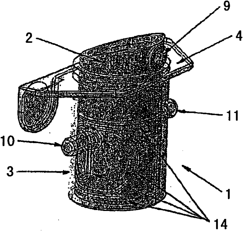
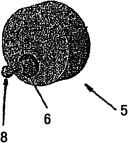
[0053] According to one embodiment of the present invention, figure 1 A positive displacement pump 1 is shown, comprising a cylindrical piston 2 and a hollow cylinder 3 mounted on a bracket 4 . The cylinder 3 has an upper open end into which the piston 2 is slidably fitted. The piston 2 is actuated by a rotor 5 bearing an eccentric shaft 6 mounted to a spring 7 .

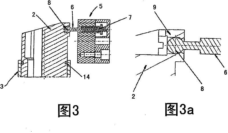
[0054] Such as image 3 and Figure 3a As shown, the shaft 6 terminates in a spherical end 8 which is clamped within a piston housing 9 to convert the angular motion of the rotor 5 into bi-directional linear and angular motion of the piston 2 . The piston 2 slides reciprocally inside the cylinder 3 while having bidirectional angular motion. The shaft 6 transmits the movement of the piston 2 inside the cylinder 3 as described below, while at the same time the spring 7 ensures smooth articulation of the tip 8 in the housing 9 . arrived at piston 2 Figure 4 and Figure 6 At the end of the suction and push strokes...


PUM


Abstract

In one embodiment, a volumetric pump in a medical fluid delivery system comprises at least one piston in a hollow cylinder, the pump having at least one inlet port through which a medical fluid can be sucked into a pump chamber during an instroke of said piston, and at least one outlet port through which the medical fluid can be expelled during an outstroke of the piston. The piston or the hollowcylinder can be actuated directly or indirectly by a rotor. This rotor transmits on the one hand a bi-directional linear movement to the piston or to the cylinder and on the other hand, a bi-directional angular movement either to the piston or to another rotable element in order to open and close alternately the inlet and outlet ports.

Description

technical field [0001] The present invention relates to volumetric pumps which may be used in drug or fluid delivery pumps such as infusion pumps, IV pumps, enteral nutrition pumps or parenteral nutrition pumps. The volumetric pump can also be used in contrast medium injection systems for medical use. Background technique [0002] Piston pumps with fluid modules are already part of the prior art. US 2004 / 101426 discloses a device comprising a cylindrical piston chamber containing a rotatable and axially displaceable pump piston with a specific gradient in profile at its upper and lower ends. The upper and lower end surfaces of the piston have been contoured to operate in contact with the respective two end surfaces of the chamber as the piston rotates. This rotation causes the piston to move alternately upwards and downwards, which allows fluid to be unidirectionally drawn into and unidirectionally expelled from the pump chamber, respectively. The rotatable movement of th...

Claims


Application Information

Patent Timeline
Patent Type & Authority Patents(China)
IPC IPC(8): F04B1/02A61M5/142
CPCF04B7/04A61M5/1422F04B1/02F04B13/00A61M5/16827A61M5/14216A61M5/007
Inventor K·莫希丁T·纳瓦罗F·朱诺
Owner ACIST MEDICAL SYST
Why Eureka
Try Eureka