Broadband directional coupler
A directional coupler and broadband technology, applied in the field of couplers, can solve the problems of large amount of index debugging, poor coupler directivity and standing wave ratio, and insignificant effect of spacing, so as to improve power capacity, improve processing speed, and improve The effect of third-order intermodulation
- Summary
- Abstract
- Description
- Claims
- Application Information
AI Technical Summary
Problems solved by technology
Method used
Image
Examples
Embodiment 1
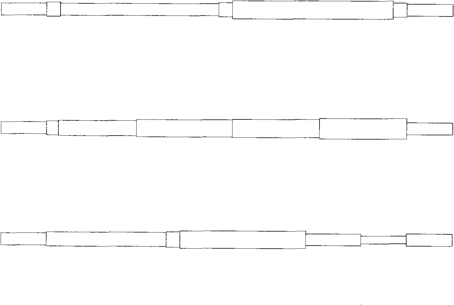
[0024] Such as figure 1 shown.
[0025] Broadband directional coupler, including cavity 1, cavity 1 is placed with conductor main line and conductor sub-line, conductor main line and conductor sub-line are divided into conductor main line main body 4, conductor main line connecting body 5, 6 and conductor sub-line main body 7, conductor The auxiliary wire connectors 8, 9, the conductor main wire connectors 5, 6 and the conductor auxiliary wire connectors 8, 9 are respectively connected with four conductor connectors 5, 6, 8, 9 by bolts or pins. The conductor main line main body 4 and the conductor secondary line main body 7 are parallel to the bottom surface of the cavity 1 . The conductor main line main body 4 and the conductor secondary line main body 7 are on the same horizontal plane and parallel to each other. The cross-sectional shape of the conductor main line main body 4 and the conductor auxiliary line main body 7 is circular; right angle. Segments of concentric c...
Embodiment 2
[0027] Such as figure 2 shown.
[0028] Broadband directional coupler, including cavity 1, cavity 1 is placed with conductor main line and conductor sub-line, conductor main line and conductor sub-line are divided into conductor main line main body 4, conductor main line connecting body 5, 6 and conductor sub-line main body 7, conductor The auxiliary wire connectors 8, 9, the conductor main wire connectors 5, 6 and the conductor auxiliary wire connectors 8, 9 are respectively connected with four conductor connectors 5, 6, 8, 9 by bolts or pins. The conductor main line main body 4 and the conductor secondary line main body 7 are parallel to the bottom surface of the cavity 1 . The conductor main line main body 4 and the conductor secondary line main body 7 are on the same horizontal plane and parallel to each other. The cross-sectional shape of the conductor main line main body 4 and the conductor auxiliary line main body 7 is circular; right angle. A re-entry section body...
PUM
| Property | Measurement | Unit |
|---|---|---|
| Angle | aaaaa | aaaaa |
Abstract
Description
Claims
Application Information
 - Generate Ideas
- Intellectual Property
- Life Sciences
- Materials
- Tech Scout
- Unparalleled Data Quality
- Higher Quality Content
- 60% Fewer Hallucinations
Browse by: Latest US Patents, China's latest patents, Technical Efficacy Thesaurus, Application Domain, Technology Topic, Popular Technical Reports.
© 2025 PatSnap. All rights reserved.Legal|Privacy policy|Modern Slavery Act Transparency Statement|Sitemap|About US| Contact US: help@patsnap.com


