
Method and device for measuring temperature and heat flow distribution on internal face of combustion chamber

A technology of heat flow distribution and measuring device, which is applied in the direction of measuring device, thermometer parts, thermometer, etc., to achieve the effect of wide application range, convenient use, convenient installation and disassembly

Inactive Publication Date: 2009-12-23
BEIHANG UNIV
View PDF0 Cites 30 Cited by
  • Summary
  • Abstract
  • Description
  • Claims
  • Application Information

AI Technical Summary

Problems solved by technology

The problem to be solved in the present invention is to use a well-developed casing-type thermocouple to measure the temperature of the wall surface, and the thermocouple can be easily disassembled; a blind hole scheme is adopted in the body of the combustion chamber, and the temperature measurement point is located at the bottom of the hole to solve the problem. Difficulties in processing, installing and sealing the combustion chamber; adopt a thermocouple fastening device to realize the positioning of the thermocouple and make the temperature measuring head in close contact with the temperature measuring point; A data processing method to obtain the inner wall surface temperature and heat flow data

Method used


Image

  • Method and device for measuring temperature and heat flow distribution on internal face of combustion chamber
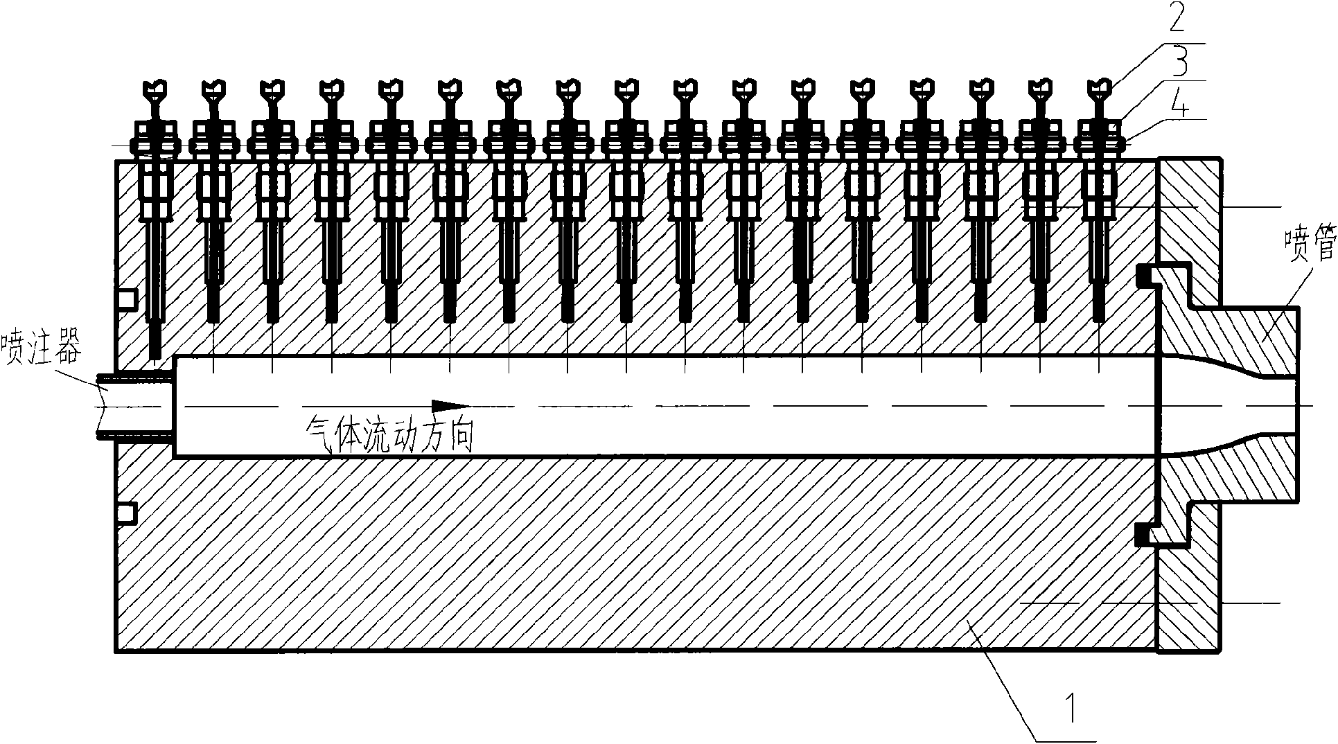
  • Method and device for measuring temperature and heat flow distribution on internal face of combustion chamber
  • Method and device for measuring temperature and heat flow distribution on internal face of combustion chamber

Examples


Embodiment Construction

[0021] The present invention will be further described below with reference to the accompanying drawings.

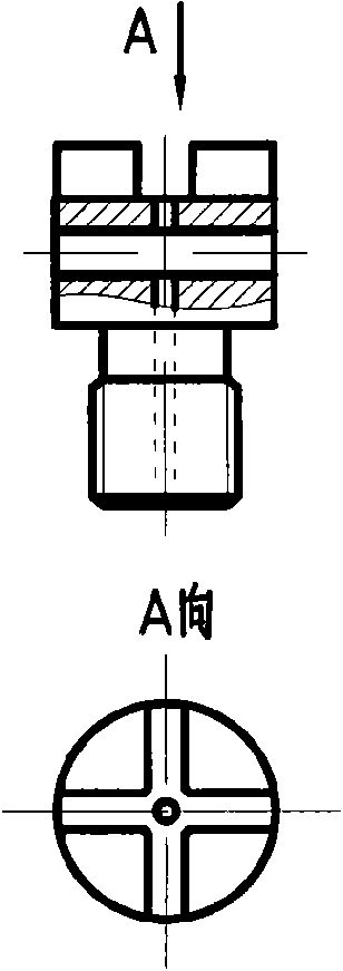
[0022] The device used to implement this measurement method mainly includes: a combustion chamber body 1 with a temperature measuring hole, a thermocouple temperature sensor 2 and a thermocouple fixing device (comprising a fastening nut 3 and a fastening screw 4). Before the experiment, extend the thermocouple probe into the temperature measuring hole, make the probe closely contact with the temperature measuring point on the solid wall, and fix the position of the thermocouple with the thermocouple fixing device. The temperature of each measuring point inside the combustion chamber wall can be collected during the experiment.

[0023] Such as figure 1 As shown, the temperature measuring holes are arranged in a straight line along the axial direction. Except for the temperature measuring point on the head, the depth, diameter and structure of each temperature measuring ...


PUM


Abstract

The invention relates to a method and a device for measuring temperature and heat flow distribution on the internal face of a combustion chamber, and belongs to the field of temperature and heat flow measurement. The measurement device comprises the combustion chamber, a temperature sensor, a temperature sensor fixing device, a signal transmission line and a computer; the lateral surface of the combustion chamber is provided with a series of equidistant temperature measuring blind holes; the temperature sensor measures the temperatures of the bottoms of the blind holes so as to obtain a temperature output curve of each measure point; and then a certain value computational method is adopted to calculate the temperature and the heat flow distribution on the internal face of the combustion chamber. Due to adopting a proposal of measuring the temperatures of the blind holes, the method and the device solve the problems of high processing and mounting difficulties, inconvenient detachment and the like in the prior art; and the armored thermocouple temperature sensor with mature technology is adopted, so that the cost is low and the use is convenient. The method and the device can be used for measuring the temperature and the heat flow distribution on the internal face of a combustion device with an axial symmetry structure.

Description

【Technical field】 [0001] The invention relates to a measurement method and device for obtaining the temperature and heat flow distribution of the inner wall of a combustion chamber. The invention is especially used for obtaining the inner wall temperature and heat flow distribution of the axisymmetric structure combustion chamber of the rocket engine when it works stably. 【Background technique】 [0002] In the development process of rocket engine combustion chamber, in order to obtain good thermal protection effect, the heat transfer characteristics of the combustion chamber, that is, the distribution of inner wall surface temperature and heat flow, is one of the key investigation contents. [0003] In the research on the heat transfer characteristics of the combustion chamber, the heat capacity type combustion chamber structure is generally used, and the test time is set at a few seconds, and the temperature sensor device is used to measure the temperature and heat flow dis...

Claims


Application Information

Patent Timeline
Patent Type & Authority Applications(China)
IPC IPC(8): G01K7/02G01K1/14
Inventor 蔡国飙汪小卫金平杜正刚高玉闪肖肖
Owner BEIHANG UNIV
Learn More