
Transmission system for grate cooler, transmission structure and grate cooler

A transmission system, grate cooler technology, applied in lighting and heating equipment, treatment of discharged materials, furnaces, etc., can solve the problems of poor operation reliability, difficult maintenance, complex structure, etc., to achieve high reliability, simple maintenance, The effect of fewer parts

Inactive Publication Date: 2010-12-08
高玉宗
View PDF4 Cites 0 Cited by
  • Summary
  • Abstract
  • Description
  • Claims
  • Application Information

AI Technical Summary

Problems solved by technology

[0004] In order to solve the problems of complex structure, cumbersome installation, many lubrication points, difficult maintenance and poor operation reliability of the transmission system for the grate cooler in the prior art, the present invention provides a transmission system for the grate cooler, which has a simple structure, Easy installation, low maintenance frequency, and high operational reliability; the present invention also provides a transmission structure and a grate cooler using the transmission system, and the transmission structure and the grate cooler have the same beneficial technical effect

Method used


Image

  • Transmission system for grate cooler, transmission structure and grate cooler
  • Transmission system for grate cooler, transmission structure and grate cooler
  • Transmission system for grate cooler, transmission structure and grate cooler

Examples


Embodiment 1

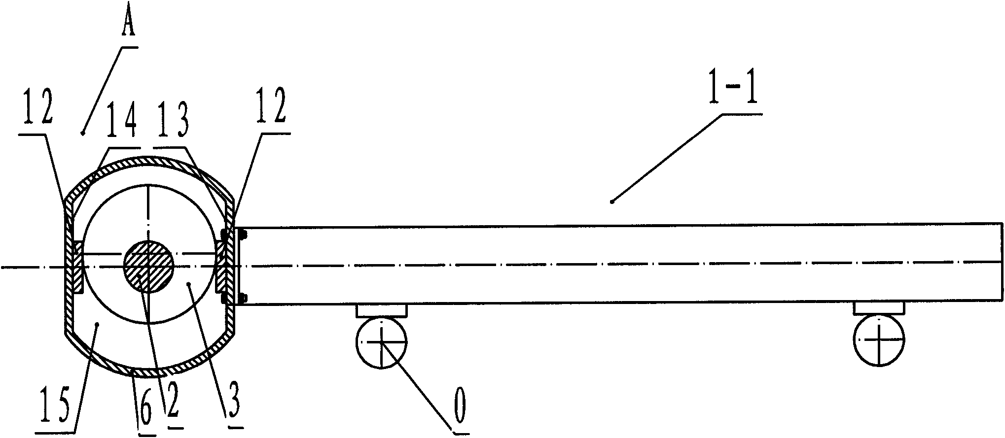
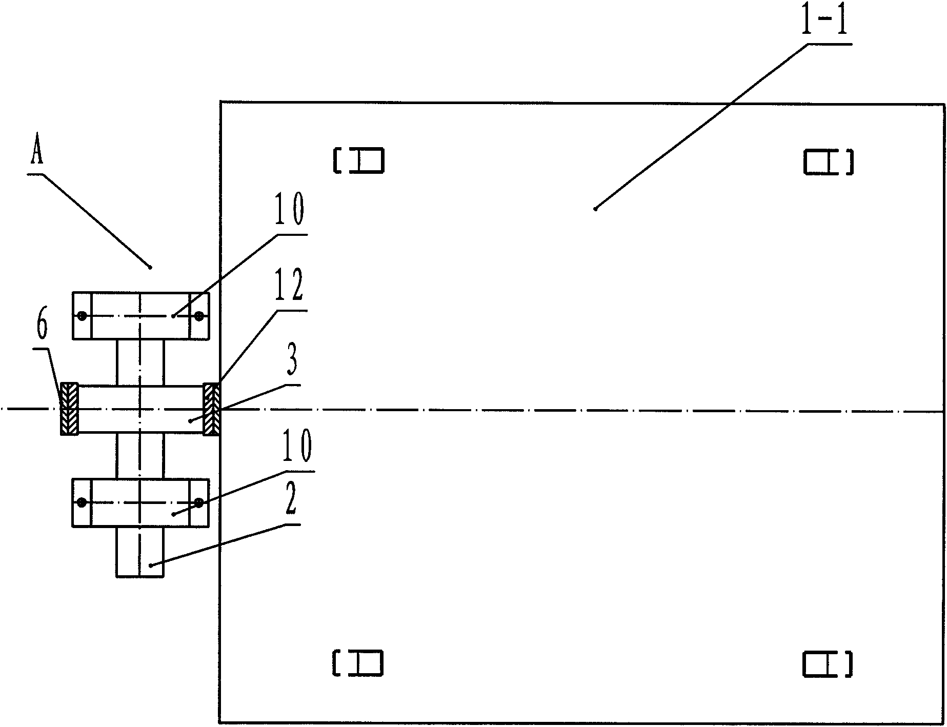
[0048] Such as figure 1 and figure 2 As shown, it is a structural schematic diagram of the first embodiment of the transmission system of the grate cooler of the present invention connected with the mobile trolley. The transmission system A is set in the middle of the rear end of the mobile trolley 1-1 (assuming that the material conveying direction is to the right in the figure, no special instructions, the same below), driven by the power system, it drives the mobile trolley 1-1 on the supporting wheel 0 for horizontal reciprocating motion, thereby driving the grate bed set on the moving trolley for horizontal reciprocating motion to cool and transfer hot clinker. The transmission system A includes an eccentric shaft 2 arranged laterally along the material conveying direction, and a cylindrical eccentric wheel 3 adapted to the eccentric shaft 2 (the eccentric shaft 2 and the eccentric wheel 3 may also be integrally structured, the same below ), two bearing housings 10 and...

Embodiment 2

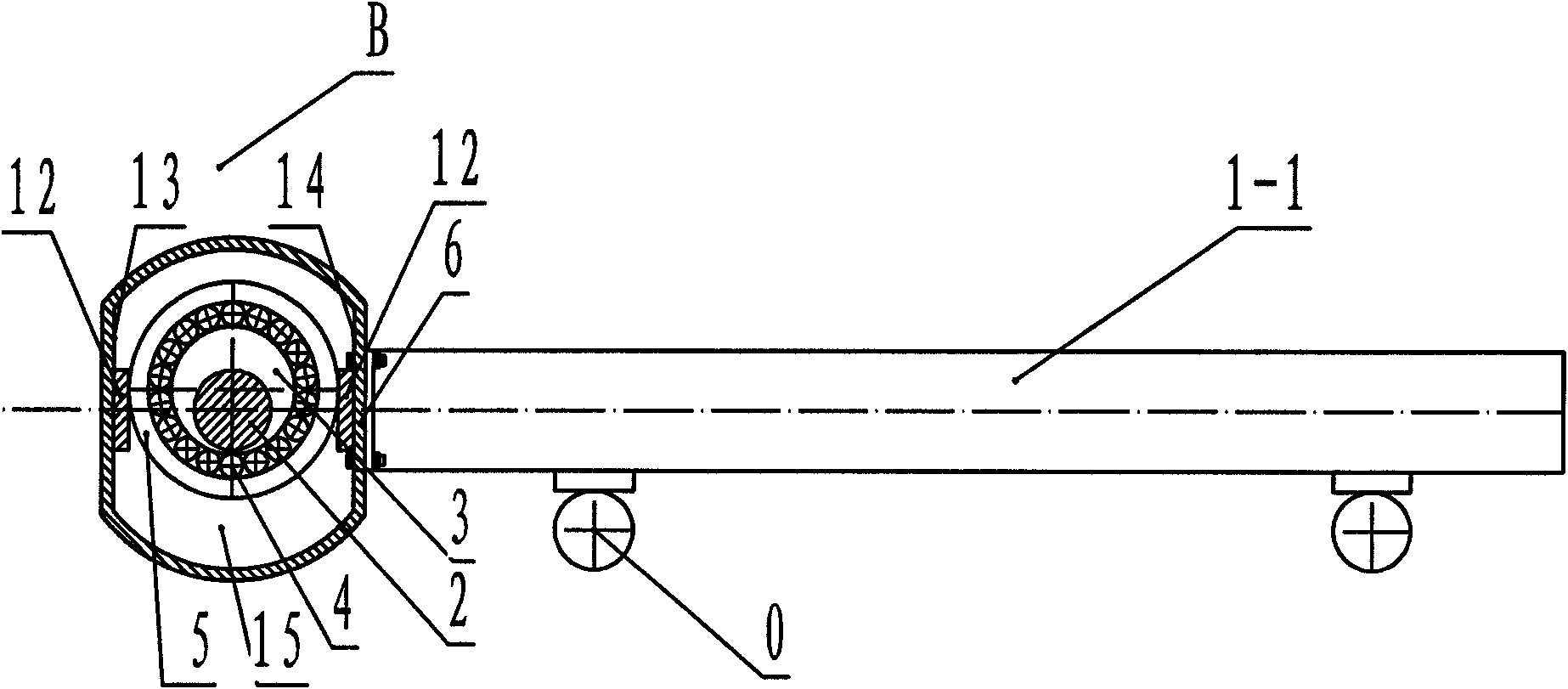
[0051] Such as image 3 As shown, it is a structural schematic diagram of the second embodiment of the grate cooler of the present invention connected to the mobile trolley. The transmission system B is arranged in the middle part of the front end of the mobile trolley 1-1 (in this embodiment, the material transmission direction is to the left in the figure), the difference between the transmission system B and the transmission system A is that the transmission system B also includes a bearing 4 and an outer wheel 5 , the outer wheel 5 is sleeved on the outer periphery of the eccentric wheel 3 through the bearing 4, the outer peripheral surface of the outer wheel 5 is a cylindrical surface (certainly also can be a drum-shaped surface), and the eccentric wheel 3 is placed on the front and rear inner surfaces 13 together with the bearing 4 and the outer wheel 5. 14 constitutes the accommodation space 15, and the front and rear inner surfaces 13, 14 are respectively fixed with fl...

Embodiment 3

[0054] Such as Figure 4 As shown, it is a schematic structural view of the third embodiment of the present invention connected to the mobile trolley (in this embodiment, the material conveying direction is to the left in the figure). The transmission system C is set between the mobile trolley 1-1 and the mobile trolley 1-2. Driven by the power system, it simultaneously drives the mobile trolley 1-1 and the mobile trolley 1-2 to perform horizontal reciprocating motion on the supporting wheel 0, thereby Drive the grate bed set on the moving trolley to do horizontal reciprocating motion to cool and transfer hot clinker. The difference between the transmission system C and the transmission system B is that: while the rear end face of the hollow cylinder 6 is fixedly connected to the front end of the mobile trolley 1-1, the front end surface of the hollow cylinder 6 is fixedly connected to the rear end of the mobile trolley 1-2, The transmission system C pushes a certain mobile t...


PUM


Abstract

The invention provides a transmission system for a grate cooler, aims at solving the problems that the transmission system for the grate cooler in the prior art has complex structure, trivial installation, more lubricating points, large maintenance difficulty and poor running reliability and comprising an eccentric shaft, an eccentric wheel, a bearing seat and a locking mechanism; the locking mechanism comprises a front inner side surface and a rear inner side surface which are opposite and form a containing space; the eccentric wheel can freely rotate after being arranged in the containing space; the minimum distance between the opposite front inner side surface and the rear inner side surface is slightly larger than the diameter of the eccentric wheel; the locking mechanism also comprises a fixed structure which is separated from the eccentric shaft and the eccentric wheel and is used for being fixedly connected with the moving cart and fixing the opposite position between the frontinner side surface and the rear inner side surface. The transmission system has simple structure, convenient installation, low maintenance frequency and high running reliability. The invention also provides a transmission structure applying the transmission system and the grate cooler simultaneously, which have same beneficial and technical effects.

Description

technical field [0001] The invention relates to a grate cooler, in particular to a transmission system for a grate cooler, a transmission structure using the transmission system, and a grate cooler. Background technique [0002] As we all know, the grate cooler is the main equipment supporting the clinker burning system of the cement plant, which plays the role of cooling and conveying the hot clinker. Because it works in the environment of high temperature, high dust and changing working conditions, and its mechanism is complicated, the operation is difficult, and the failure rate is high. Therefore, its continuous, stable and reliable operation is the key that directly affects the kiln operation rate. [0003] Grate coolers can be divided into three types: vibration type, rotary type and push type according to the movement mode of the grate plate. During the development of the cement industry, with the large-scale production and the summary of practice, the vibrating grat...

Claims


Application Information

Patent Timeline
Patent Type & Authority Patents(China)
IPC IPC(8): F27D15/02C04B7/47
Inventor 高玉宗
Owner 高玉宗
Learn More