Mechanically sealing device for main circulating pump for seawater desulfuration

A technology of mechanical sealing device and main circulation pump, which is applied in the direction of mechanical equipment, pumping device components for elastic fluid, pumps, etc., and can solve the problem of reducing the working temperature of the seal, uneven cooling of the seal, and reduced sealing performance, etc. question

Inactive Publication Date: 2009-12-23
蒋敏
View PDF0 Cites 3 Cited by
  • Summary
  • Abstract
  • Description
  • Claims
  • Application Information

AI Technical Summary

Problems solved by technology

[0002] At present, the State Intellectual Property Office of China has published an invention named "Desulfurization Cartridge Mechanical Seal with Circulating Cooling Water" on the Internet. In this invention, there is an annular inner seal between the static ring system and the outer wall of the shaft sleeve cavity, and the outer wall of the spring seat is provided with a flushing liquid inlet hole and a flushing liquid outlet hole communicating with the annular inner cavity. Although this structure not only overcomes the cavitation phenomenon caused by the desulfurization pump during operation It causes the dry friction of the sealing end face to cause the defect of the seal wear, and also plays a role in reducing the working temperature of the seal, that is, the static ring and the moving ring, but it still has a disadvantage: because the flushing liquid in the invention enters the There is only one hole, and the annular inner cavity has a certain axial length. In other words, there is a certain distance between the position of the flushing fluid inlet hole and the sealing surface, so the external flushing fluid usually cannot be flushed immediately. It has a cooling effect on the sealing surface, and because there is only one flushing liquid inlet hole, it is easy to cause uneven cooling of the seal, which affects the working state and reduces the sealing performance

Method used


Image

  • Mechanically sealing device for main circulating pump for seawater desulfuration
  • Mechanically sealing device for main circulating pump for seawater desulfuration

Examples


Embodiment Construction

[0009] The present invention will be further described in detail below in conjunction with the accompanying drawings and specific embodiments.

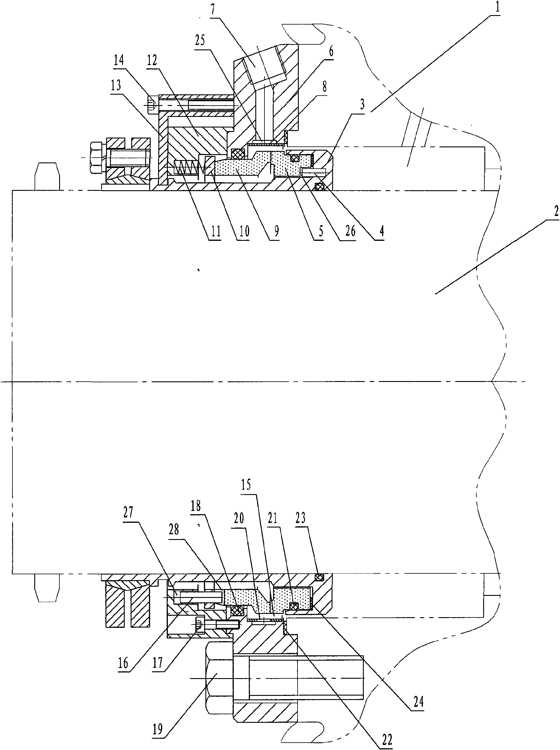
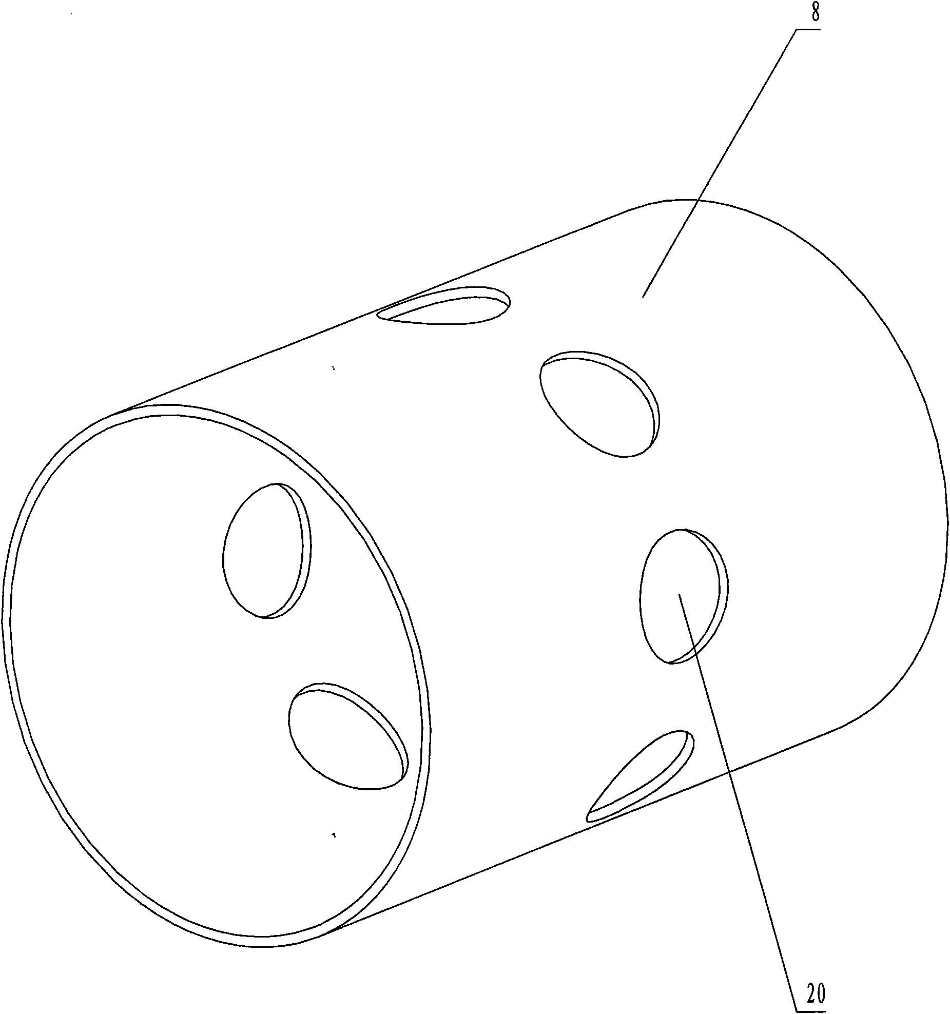
[0010] like figure 1 , figure 2 As shown, in this specific embodiment, the mechanical seal device for the seawater desulfurization main circulation pump of the present invention includes a moving ring assembly, a static ring assembly, a seal seat 6, a spacer sleeve 8 and a shaft sleeve 3 tightly matched with the pump shaft 2; An O-ring 23 is provided at the joint between the right end of the shaft sleeve 3 and the pump shaft 2; the moving ring assembly is connected to the shaft sleeve 3; the static ring assembly is connected to the seal seat 6; the moving ring assembly includes a moving ring 5, The transmission pin 4 and the moving ring O-ring 21 and the washer 24 arranged between the moving ring 5 and the shaft sleeve 3; one end of the transmission pin 4 is connected to the shaft sleeve 3, and the other end is located In the drive...


PUM


Abstract

The invention discloses a mechanically sealing device for a main circulating pump for seawater desulfuration, comprising a sealing seat (6), a shaft sleeve (3) tightly matched with a pump shaft (2), a movable ring assembly connected with the shaft sleeve (3), a static ring assembly connected with the sealing seat (6) and a spacer bush (8) provided with a flushing hole (20), wherein, the sealing seat (6) provided with a flushing water path (7) is connected with a pump body (1); the inner wall of the shaft sleeve (3) is provided with an annular water channel (25) communicated with the flushing water path (7); the spacer bush (8) is connected to the sealing seat (6) on the annular water channel (25); a flushing cavity (15) is arranged among the movable ring assembly, the static ring assembly and the spacer bush (8); the flushing hole (20) is communicated with the annular water channel (25) and the flushing cavity (15); the position of the flushing hole (20) and the position of the annular water channel (25) correspond to a sealing surface (29).The invention can avoid the dry friction of a sealing end surface, and simultaneously can ensure that the cooling of the sealing surface is evener with more favourable cooling effect so as to effectively ensure sealing performance.

Description

technical field [0001] The invention relates to a mechanical seal device for a seawater desulfurization main circulation pump. Background technique [0002] At present, the State Intellectual Property Office of China has published an invention named "Desulfurization Cartridge Mechanical Seal with Circulating Cooling Water" on the Internet. In this invention, there is an annular inner seal between the static ring system and the outer wall of the shaft sleeve cavity, and the outer wall of the spring seat is provided with a flushing liquid inlet hole and a flushing liquid outlet hole communicating with the annular inner cavity. Although this structure not only overcomes the cavitation phenomenon caused by the desulfurization pump during operation It causes the dry friction of the sealing end face to cause the defect of the seal wear, and also plays a role in reducing the working temperature of the seal, that is, the static ring and the moving ring, but it still has a disadvanta...

Claims


Application Information

Patent Timeline
IPC IPC(8): F04D29/10F04D29/58
Inventor 蒋敏
Owner 蒋敏
Why Eureka
Try Eureka