Motor control device
A control device, motor technology, applied in the direction of single motor speed/torque control, current controller, electronic commutator, etc.
- Summary
- Abstract
- Description
- Claims
- Application Information
AI Technical Summary
Problems solved by technology
Method used
Image


Examples
no. 1 approach
[0062] refer to Figure 1 ~ Figure 3 , the first embodiment applied to the control of the fan motor of the air conditioner will be described.
[0063] figure 1 is the block wiring diagram of the motor control device, and Figure 10 The difference from the previous device is that instead of Figure 10 The phase angle signal generation circuit 11 is provided with a phase adjustment circuit 18A.
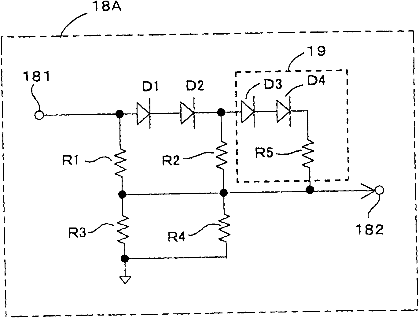
[0064] phase adjustment circuit 18A as figure 2 As shown in the connection diagram, the circuit consists of multiple resistors R1~R4 and multiple diodes D1, D2 (the inflection point is approximated by a broken line with one point α) or, further, a combination of resistor R5, diodes D3, D4 is added Circuit (when the inflection point is approximated by a broken line of two points α, β). Then, the speed command voltage of the speed signal generation circuit 5 applied to the input terminal 181 is processed into a voltage having a broken-line approximation characteristic, and a phase an...
no. 2 approach
[0074] refer to figure 1 as well as Figure 4 , Figure 5 A second embodiment applied to the control of a washing machine motor as an example of a low-rotation high-torque motor will be described. Figure 4 is a wiring diagram of the phase adjustment circuit 18B, Figure 5 It is an explanatory diagram of the characteristics of the phase angle signal with respect to the rotational speed of the washing machine motor.
[0075] The motor control device of the present embodiment is configured by figure 1 The phase adjustment circuit 18A is replaced by Figure 4 The phase adjustment circuit 18B.
[0076] Furthermore, when the brushless DC motor 1 is a washing machine motor of a low-rotation high-torque type, the optimal phase angle control characteristic (the optimal phase of energization corresponding to the torque) corresponding to its rotational speed (speed of the brushless DC motor 1) The characteristic of the angle value) is Figure 5 The nonlinear characteristics of ...
no. 3 approach
[0085] refer to figure 1 as well as Image 6 , Figure 7 A third embodiment corresponding to the third aspect of the present invention will be described. Image 6 is a wiring diagram of the phase adjustment circuit 18C, Figure 7 It is an explanatory diagram of the characteristics of the phase angle signal with respect to the rotational speed of the fan motor.
[0086] This embodiment is configured to be applied to the control of the fan motor of the air conditioner similar to the first embodiment, and for the motor control device, the figure 1 The phase adjustment circuit 18A is replaced by Image 6 The phase adjustment circuit 18C.
[0087] phase adjustment circuit 18C with figure 2 The phase adjustment circuit 18A differs in that the resistor R2 of the phase adjustment circuit 18A is replaced by a positive temperature coefficient (PTC) thermistor Rth whose resistance value changes according to the temperature change of the brushless DC motor 1 .
[0088] In this c...
PUM
 Abstract
Description
Claims
Application Information
 - R&D
- Intellectual Property
- Life Sciences
- Materials
- Tech Scout
- Unparalleled Data Quality
- Higher Quality Content
- 60% Fewer Hallucinations
Browse by: Latest US Patents, China's latest patents, Technical Efficacy Thesaurus, Application Domain, Technology Topic, Popular Technical Reports.
© 2025 PatSnap. All rights reserved.Legal|Privacy policy|Modern Slavery Act Transparency Statement|Sitemap|About US| Contact US: help@patsnap.com