Method for testing parameters of synchronous motor and device for achieving same
A technology for synchronous motor and parameter testing, which is applied in the direction of motor generator testing, measuring devices, and measuring electricity. It can solve problems such as strong dependence on drive performance, inability to measure and obtain various parameters at the same time, and complex torque coefficient testing methods. , to achieve the effects of improving measurement accuracy, convenient operation, and simple system structure
- Summary
- Abstract
- Description
- Claims
- Application Information
AI Technical Summary
Problems solved by technology
Method used
Image

Examples
specific Embodiment approach 1
[0011] Specific implementation manner 1: The process of the synchronous motor parameter testing method described in this implementation manner is:
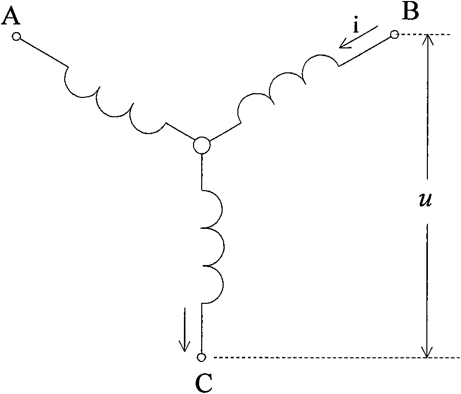
[0012] Measure the AC and DC axis inductance L of the tested synchronous motor winding q , L d , The specific process is: to pass a single-phase AC current into any two phases of the three-phase windings of the synchronous motor under test i = 2 I sin ωt , Use external force to drive the rotor of the tested synchronous motor to rotate at a constant speed for more than one revolution. During the rotation of the tested synchronous motor, measure the voltage u at both ends of the energized winding, and decompose and calculate the effective value of the fundamental wave voltage of the measured voltage, and then take out all fundamental wave voltages Maximum value U among effective values max1 , Minimum U min1 , Then the quadrature axis and direct ...
specific Embodiment approach 2
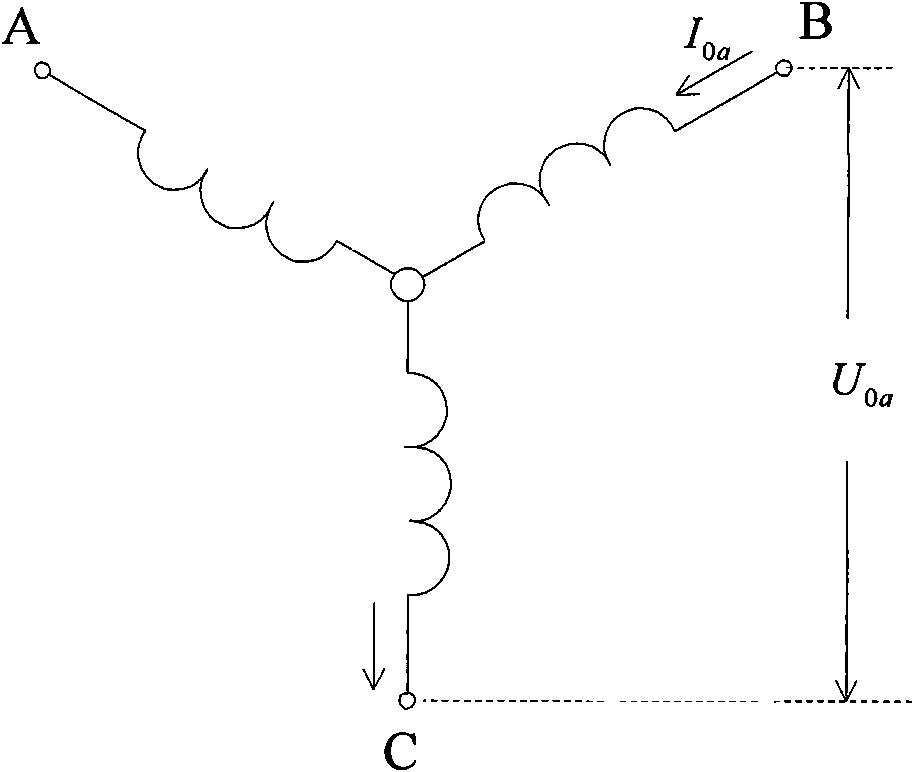
[0021] Specific embodiment 2: The synchronous motor parameter test method described in this embodiment is based on the test method described in specific embodiment 1, adding the measurement of the DC resistance R of each phase winding of the synchronous motor under test. 0a The specific process is as follows: Direct current I is applied to any two-phase winding of the three-phase winding of the synchronous motor under test 0a , Collect and obtain the DC voltage U at both ends of the two-phase winding with DC current 0a , Then the DC resistance of the single-phase winding of the tested synchronous motor is: R 0 a = U 0 a 2 I 0 a .
[0022] The DC current I is applied to any two-phase windings...
specific Embodiment approach 3
[0023] Specific implementation mode 3: The synchronous motor parameter testing method described in this implementation mode is based on the testing method described in specific implementation mode 1, adding the back EMF coefficient K of the tested synchronous motor E The specific process is: use external force to drive the tested synchronous motor to rotate at a constant speed of n, and collect the effective value E of the fundamental wave of the electromotive force at both ends of any two-phase winding in the tested synchronous motor during the rotation of the tested synchronous motor. 0 , To obtain the back EMF coefficient of the tested synchronous motor K E = E 0 3 n .
[0024] For the electromotive force at both ends of any two-phase winding described in this embodiment, see Figure 4 As shown, it refers to...
PUM
 Abstract
Description
Claims
Application Information
 - R&D
- Intellectual Property
- Life Sciences
- Materials
- Tech Scout
- Unparalleled Data Quality
- Higher Quality Content
- 60% Fewer Hallucinations
Browse by: Latest US Patents, China's latest patents, Technical Efficacy Thesaurus, Application Domain, Technology Topic, Popular Technical Reports.
© 2025 PatSnap. All rights reserved.Legal|Privacy policy|Modern Slavery Act Transparency Statement|Sitemap|About US| Contact US: help@patsnap.com