Stirring pile-grafting machine

A pile planting machine and pile planting technology, applied to sheet pile walls, buildings, foundation structure engineering, etc., can solve the problems of not being able to guarantee the verticality of the aggregate, poor machine stability, and easy deviation, and achieve a simple and easy construction process. Operation, compact structure, not easy to dump

Inactive Publication Date: 2009-12-16
广东永基建筑基础股份有限公司
View PDF1 Cites 4 Cited by
  • Summary
  • Abstract
  • Description
  • Claims
  • Application Information

AI Technical Summary

Problems solved by technology

For example, the patent No. is the invention of 00215786.1, which provides a kind of deep mixing pile reinforcement construction equipment. In this equipment, a fixed pulley is fixed on the top of the frame, and a horizontal beam is fixed at the same time. The pulley block is connected with a vibratory hammer and a fixture; this equipment is based on the traditional mixing pile machine with an additional vibratory hammer and fixture, which is mainly used to insert steel bars and other aggregates into the mixing pile, but the whole equipment only has the mixing pile machine part A central line and the vibratory hammer is hung by the weight protruding from the bracket, which makes the whole machine less stable and easy to shake, and the force that the vibratory hammer can exert cannot be too large, otherwise it is easy to fall over, so when it is necessary to insert it into the mixing pile For larger prefabricated piles or when the aggregate needs to be inserted deeper or even beyond the bottom of the mixing pile, the machine is powerless; and because the vibratory hammer has no fixing device, it is easy to shift during the process of inserting the aggregate, so that the insertion can not be ensured. The aggregate remains vertical, so the machine can therefore only be used in applications where the position of the aggregate insertion is not critical

Method used


Image

  • Stirring pile-grafting machine
  • Stirring pile-grafting machine
  • Stirring pile-grafting machine

Examples


Embodiment Construction

[0020] Specific embodiments of the present invention will be described below in conjunction with the accompanying drawings.

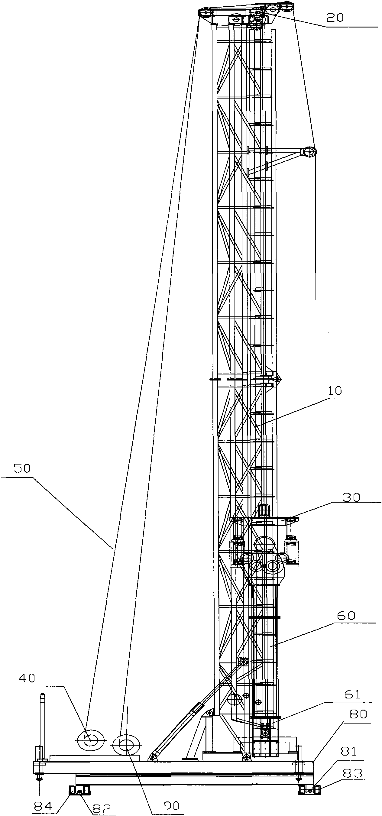
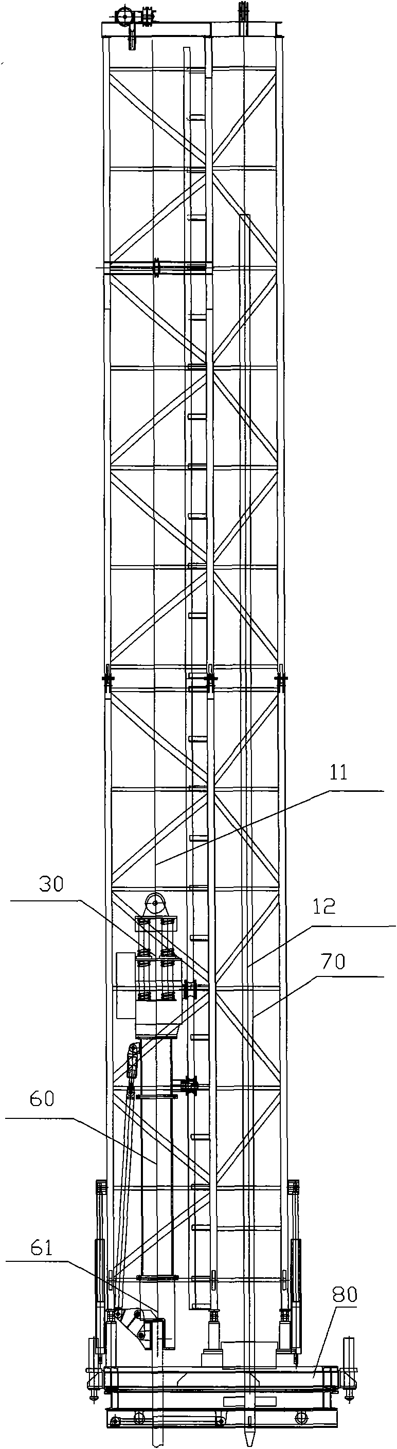
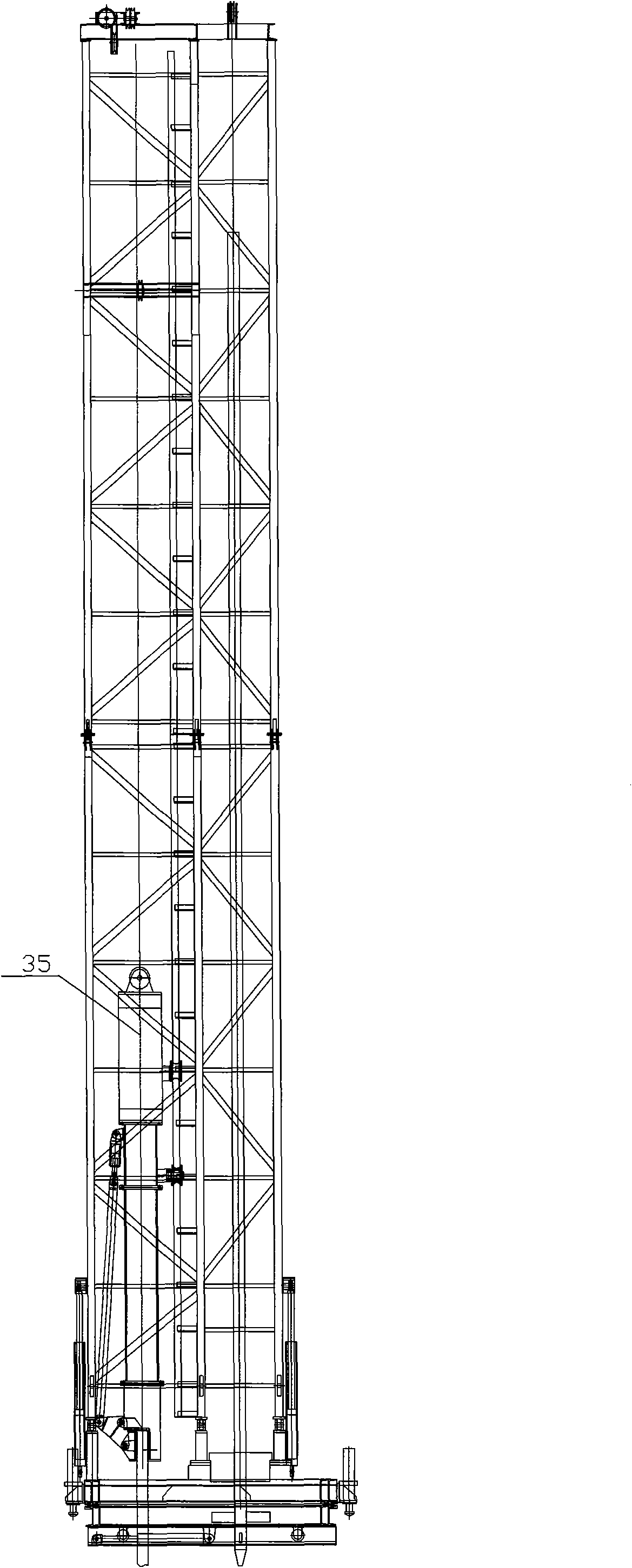
[0021] figure 1 , figure 2 Shown is the first embodiment of the stirring pile driver of the present invention. like figure 1 , figure 2 Shown, the stirring pile machine shown in this embodiment comprises:

[0022] The pile planting device comprises a power hammer, which is a vibratory hammer 30 in this embodiment, a pile planting pile feeder 60, and a power hammer lifter 40, and the top of the pile planting pile feeder 60 is fixedly connected to the top of the vibratory hammer 30. Bottom, the center of the bottom of the pile-planting pile feeder 60 is provided with a pile-planting clamping head 61 for clamping the aggregate to be implanted; the center line of the pile-planting pile feeder 60 and the center line of the vibratory hammer 30 On a straight line, of course, when the construction requirements are low in other embodiments of the present ...


PUM


Abstract

The invention provides a stirring pile-grafting machine, which is characterized by comprising the following components: a pile-grafting device, a stirring device, a support frame and a first rope; wherein, the pile-grafting device consists of a power hammer, a pile-grafting pile-delivering device and a power hammer lifter; wherein, the top end of the pile-grafting pile-delivering device is fixedly connected with the bottom part of the power hammer; the center of the bottom part of the pile-grafting pile-delivering device is provided with a pile-grafting chuck for clamping the aggregate to be grafted; the stirring device comprises a stirring pile power head, a clutch, a hydraulic station, a turnplate and a stirring rod; the support frame is used for supporting the stirring device and the pile-grafting device, and the top of the support frame is provided with a pulley block; the first rope is wound on the pulley block, one end thereof is connected with the top of the power hammer, and the other end thereof is connected with the power hammer lifter so that the power hammer lifter can control the up-down movement of the pile-grafting device. The stirring pile-grafting machine has simple and compact structure, which is easy for realizing the technique of grafting preformed piles in the cement-soil pile conveniently.

Description

technical field [0001] The invention relates to building construction equipment, in particular to a stirring pile driver. Background technique [0002] In the construction industry, mixing piles are widely used. There are multiple mixing pile machines in the prior art, but they can only stir soil into cement. Due to the characteristics of low strength, low compressive strength and poor bending resistance of mixing piles, they are increasingly being replaced by composite piles. [0003] Combination piles are inserted into traditional mixing piles with aggregates, such as bamboo poles, steel bars, I-beams, etc.; it can greatly enhance the compression and bending resistance of the pile, and its strength is greatly enhanced. Correspondingly in the prior art, there has been a stirring pile planting machine improved on the basis of the traditional stirring pile machine. For example, the patent No. is the invention of 00215786.1, which provides a kind of deep mixing pile reinforc...

Claims


Application Information

Patent Timeline
IPC IPC(8): E02D5/22E02D5/46E02D7/00E02D13/04
Inventor 黎志中
Owner 广东永基建筑基础股份有限公司
Why Eureka
Try Eureka