
Countercurrent pot-type reaction device for supercritical water treatment of waste organic matter

A supercritical water and reaction device technology, which is applied in the fields of solid waste removal, heating water/sewage treatment, oxidized water/sewage treatment, etc. It can solve the problems of difficult disassembly, short service life of catalysts, blockage of reactor inlet and outlet pipelines, etc. problem, achieve the effect of overcoming deposition and agglomeration, delaying corrosion rate, and compact structure

Inactive Publication Date: 2011-06-01
XI AN JIAOTONG UNIV
View PDF0 Cites 0 Cited by
  • Summary
  • Abstract
  • Description
  • Claims
  • Application Information

AI Technical Summary

Problems solved by technology

[0006] (2) The solubility of the inorganic salts contained in the reactor feed in supercritical water is extremely small, and some of the salts with high viscosity will be deposited, which will cause blockage of the reactor or its inlet and outlet pipelines, resulting in the failure of the reaction system. Forced to stop, or even a safety accident
However, in the case of high salt content in the feed, the catalyst has problems such as short service life and easy poisoning, and the catalyst needs to be replaced frequently
At present, the continuous reactor used in supercritical water treatment technology, in order to ensure good sealing, it is difficult to disassemble the structure, it is difficult to load and replace the catalyst conveniently, and at the same time, it does not consider reducing the catalyst deactivation rate from the reactor structure. Method

Method used


Image

  • Countercurrent pot-type reaction device for supercritical water treatment of waste organic matter
  • Countercurrent pot-type reaction device for supercritical water treatment of waste organic matter

Examples


Embodiment Construction

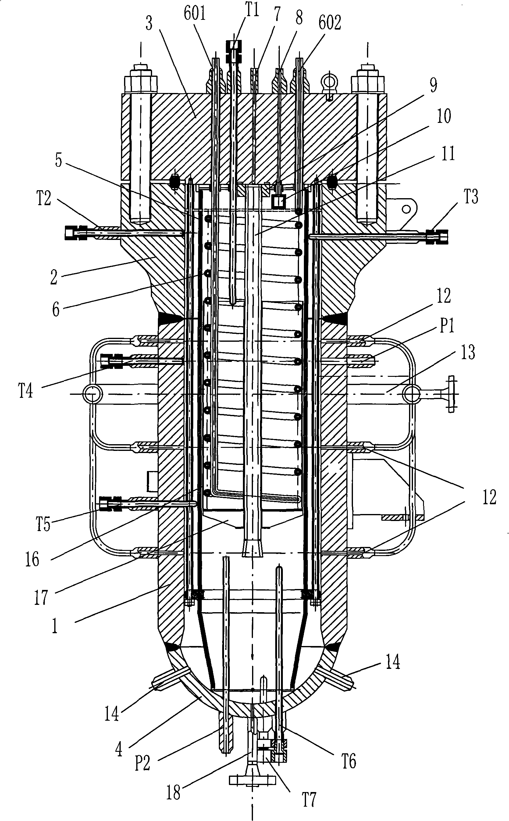
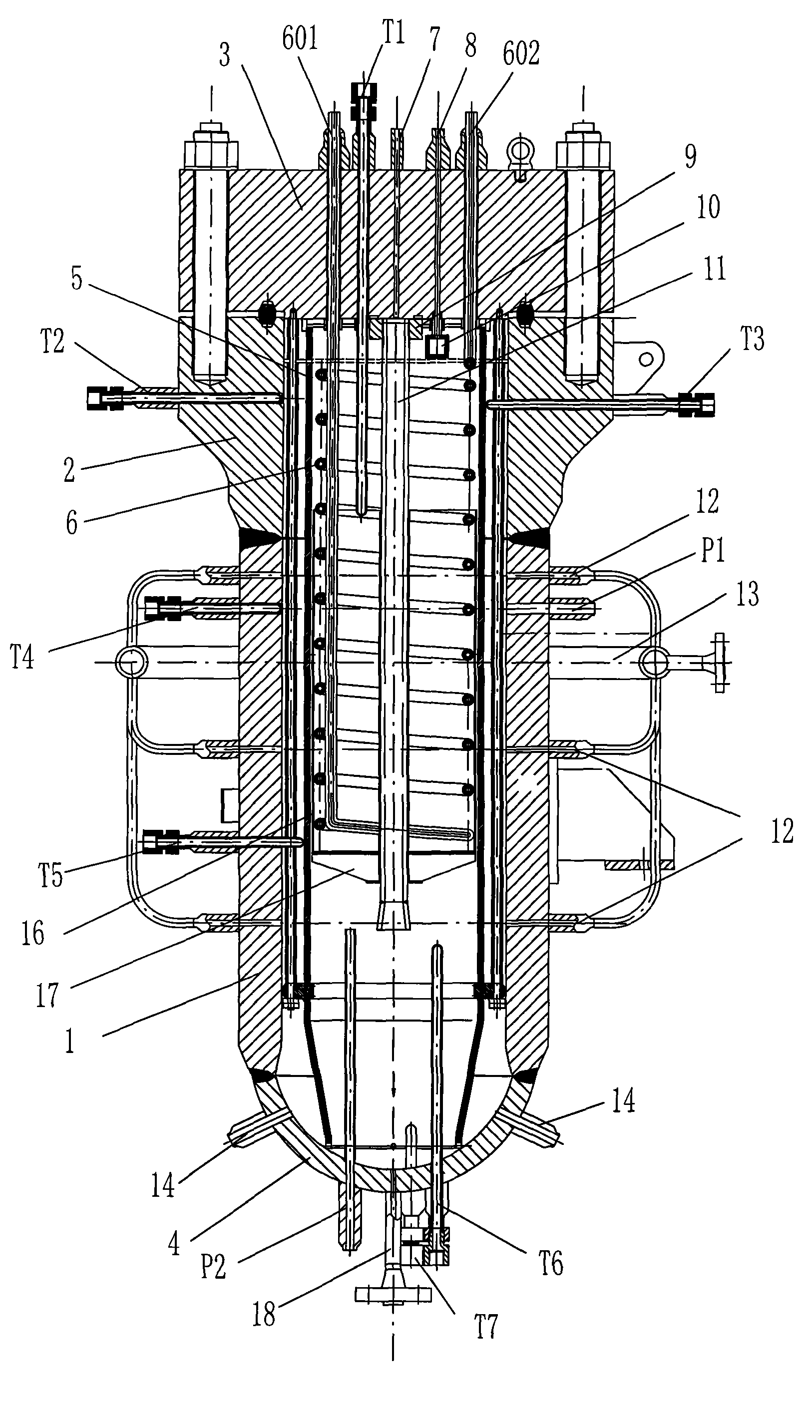
[0025] refer to figure 1 , a countercurrent tank reaction device for supercritical water treatment of waste organic matter, mainly including: a cylinder body 1, an end cover 3, a spherical head 4, an evaporation wall 5, a heat exchange coil 6, and a material inlet pipe 7, which are arranged on the end cover The central conduit 11 at the bottom, the reaction outlet pipe 8, the water inlet pipes 12 and 14 for evaporating wall water, the salt discharge pipe 18, the catalyst box 16 and related temperature and pressure sensors, etc.

[0026] The cylinder body is composed of a straight cylinder part 1 and an upper end part 2 welded, a spherical head 3 is welded on the lower end of the cylinder body straight cylinder part 1, an octagonal gasket is arranged between the cylinder upper end part 2 and the end cover 3, and it is fixed by a stud bolt . The evaporation wall 5 is made of sintered metal mesh, which is arranged in the cylinder with a gap with the inner wall of the cylinder, a...


PUM


Abstract

The invention discloses a countercurrent pot-type reaction device for supercritical water treatment of waste organic matter, comprising a barrel body, a spherical end socket (4), an end cap (3), an evaporation wall (5), a heat exchange coiled tube (6), a material inlet tube (7), a central duct (11), a reaction outlet tube (8), a middle water inlet tube (12) and a salt discharging tube (18), wherein, the barrel body is composed of a straight barrel part (1) and an upper end part (2); the spherical end socket (4) is fixed at the lower end of the straight barrel part (1) of the barrel body; the end cap (3) is fixed on the upper end part of the barrel body; the evaporation wall (5) is arranged in the barrel body and a gap is left between the inner wall of the barrel body and the evaporation wall; the heat exchange coiled tube (6) is arranged in the evaporation wall (5); the material inlet tube (7) runs through the center of the end cap (3); the central duct (11) is arranged on the bottom of the end cap (3) and is communicated with the material inlet tube (7); the reaction outlet tube (8) runs through the end cap (3) and is arranged beside the material inlet tube (7); the middle water inlet tube (12) is arranged in water in the evaporation wall of the straight barrel part (1) of the barrel body; and the salt discharging tube (18) is arranged at the bottom of the spherical end socket (4).

Description

technical field [0001] The invention belongs to the field of waste organic matter treatment, and relates to a reactor for realizing the harmless treatment and resource utilization of organic waste water by means of supercritical water oxidation or gasification, in particular to a countercurrent tank reaction for supercritical water treatment of waste organic matter device. Background technique [0002] Supercritical water refers to water in a special state whose temperature and pressure are higher than its critical point (T=374.15°C, P=22.12MPa). Supercritical water has the properties of both liquid and gaseous water. In this state, only a small amount of hydrogen bonds exist. The dielectric constant is similar to that of organic solvents. It has a high diffusion coefficient and low viscosity. Under a sufficiently high pressure, organic matter and oxygen can be miscible with supercritical water in any proportion, so that the heterogeneous reaction becomes a homogeneous reac...

Claims


Application Information

Patent Timeline
Patent Type & Authority Patents(China)
IPC IPC(8): C02F9/10B09B3/00C02F1/04C02F1/72
Inventor 王树众徐东海公彦猛郭洋马红和唐兴颖
Owner XI AN JIAOTONG UNIV
Learn More