
Double-stage oil-water separator

An oil-water separator, oil-water separation technology, applied in the direction of immiscible liquid separation, etc., can solve the problems of difficulty in designing and manufacturing oil-absorbing floats, poor separation effect, low oil removal efficiency, etc., to achieve high oil removal efficiency, manufacturing The effect of low cost and simple structure

Inactive Publication Date: 2009-12-16
YICHANG ENHANCE ULTRASONIC ELECTRIC
View PDF3 Cites 13 Cited by
  • Summary
  • Abstract
  • Description
  • Claims
  • Application Information

AI Technical Summary

Problems solved by technology

The separation effect of the former is poor, the separated oil slick contains a large amount of cleaning fluid, and the design and manufacture of the oil-absorbing float is difficult; although the latter has a good oil-water separation effect, the oil removal efficiency is low, and it is difficult to meet the needs of modern industrial production. needs

Method used


Image

  • Double-stage oil-water separator
  • Double-stage oil-water separator

Examples


Embodiment Construction

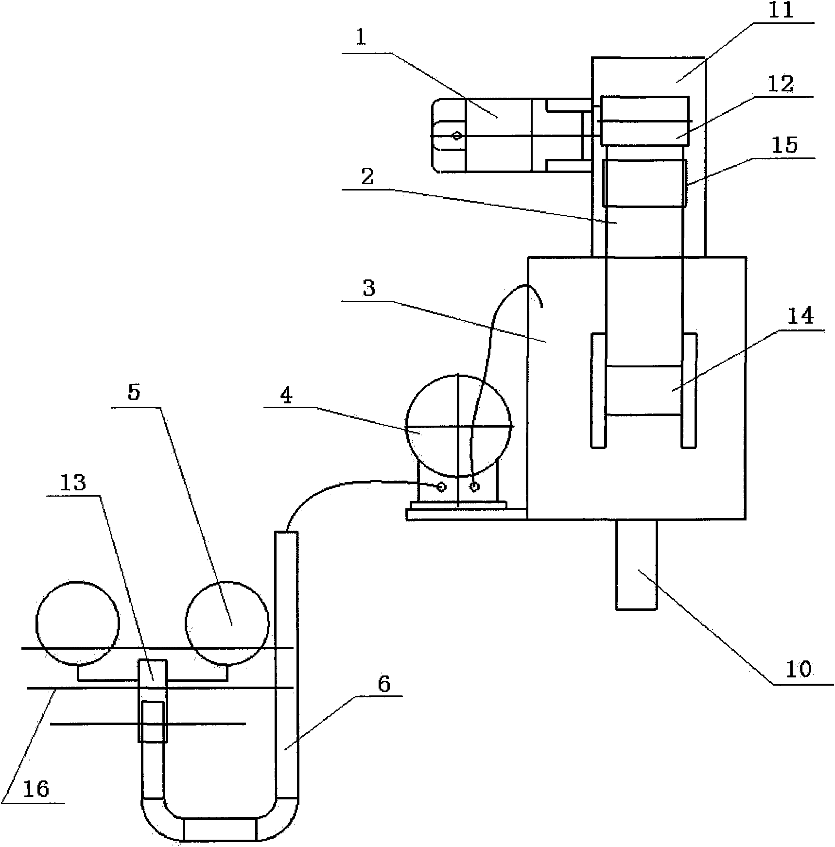
[0013] Such as figure 1 and figure 2 As shown, the present invention includes an oil-water separation chamber 3, the outlet pipe of the pump 4 communicates with the oil-water separation chamber 3, the oil-absorbing float 5 communicates with the water inlet pipe of the pump 4 through the oil-absorbing pipeline 6, and the oil-water separation chamber 3 is provided with an oil baffle 7 , The oil baffle plate 7 separates the oil-water separation chamber 3 into a clean water chamber 8 and a sewage chamber 9, an overflow device is installed in the clean water chamber 8, and the oil scraping mechanism is connected with the oil-water separation chamber 3 through a mounting bracket 11.

[0014] In the oil scraping mechanism, the power source 1 is connected with the driving wheel 12 installed on the mounting bracket 11 through the transmission mechanism, the driving wheel 12 is connected with the driven wheel 14 arranged in the sewage chamber 9 through the oil removal belt 2, and the d...


PUM


Abstract

The invention relates to a double-stage oil-water separator, comprising an oil-water separation chamber, wherein a water outlet pipe of a pump is communicated with the oil-water separation chamber, an oil suction floater is communicated with a water inlet pipe of the pump by an oil suction pipeline, an oil baffle plate is arranged in the oil-water separation chamber separating the oil-water separation chamber into a clear water chamber and a polluted water chamber, an overflow device is installed in the clear water chamber, and an oil scraping mechanism is connected with the oil-water separation chamber by an installing support. The double-stage oil-water separator of the invention combines the working principles of the existing two one-stage oil-water separators so that after an oil-water mixture extracted by the pump is primarily separated in the oil-water separation chamber, concentrated floating oil can be processed by secondary separation by the oil scraping mechanism. The double-stage oil-water separator has simple structure and high oil removal efficiency, and can greatly improve the quality of cleaning workpieces; the oil suction floater is transformed to be a sliding structure, thereby eliminating the influence of the oil suction pipeline on the weight of the floater and increasing the efficiency; and the invention also has the advantages of small volume, low manufacturing cost and convenient operation.

Description

technical field [0001] The invention relates to an oil-water separator, in particular to a two-stage oil-water separator which can separate oil-water mixture twice. Background technique [0002] The existing oil-water separator generally can only separate the oil-water mixture once, and belongs to the first-stage oil-water separator. It has two structures, one is composed of oil-absorbing float, pump, oil-water separation chamber, etc., and the pump is used to suck the oil-water mixture into the oil-water separation chamber for primary separation; the other is composed of oil-scraping mechanism, reducer, etc. Composition, using the reducer to drive the oil scraping mechanism to perform primary separation of the oil-water mixture. The separation effect of the former is poor, and the separated floating oil contains a large amount of cleaning liquid, and the design and manufacture of the oil-absorbing float is difficult; although the separation effect of the latter is good, th...

Claims


Application Information

Patent Timeline
Patent Type & Authority Applications(China)
IPC IPC(8): B01D17/02
Inventor 庄秀平高续业董清
Owner YICHANG ENHANCE ULTRASONIC ELECTRIC
Learn More