
Hermetic sealing device

A sealing device and compact technology, applied in the direction of engine sealing, engine components, mechanical equipment, etc., can solve problems such as unstable contact state, achieve the effects of suppressing sliding friction, improving bending, and reducing sliding resistance

Inactive Publication Date: 2009-12-09
NOK CORP
View PDF1 Cites 8 Cited by
  • Summary
  • Abstract
  • Description
  • Claims
  • Application Information

AI Technical Summary

Problems solved by technology

[0006] However, when using this prior art, since the parallel grooves 9 are evenly provided from the contact portion 6a to the non-contact portion 6b of the side lip 6, as Figure 10 As shown, regardless of the lip interference, a part of the parallel groove 9 is always in contact with the flinger 4, so the contact state of the side lip 6 with respect to the flinger 4 (pressure distribution on the sealing surface) will be unstable

Method used


Image

  • Hermetic sealing device
  • Hermetic sealing device
  • Hermetic sealing device

Examples


no. 1 example

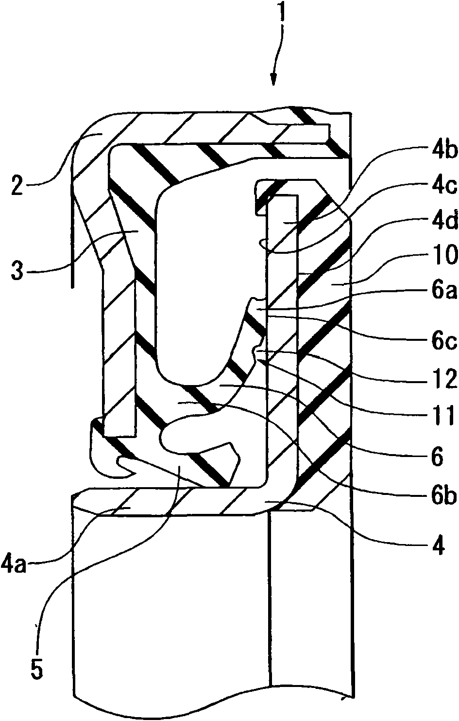
[0056] figure 1 A cross section of a main part of the sealing device 1 of the first embodiment of the present invention is shown.

[0057] The sealing device 1 of this embodiment is used, for example, as a wheel hub bearing seal (hub seal) in a bearing portion of a wheel suspension device for an automobile, and the main lip (radial lip) 5 and the side lip (end face lip) 6 are integrated. Forming, in which the main lip 5 is vulcanized and bonded to the rubber-like elastic body 3 on the mounting ring (metal ring) 2 made of steel such as metal, and slidably and tightly connected to the oil flinger (metal ring) as a sliding opposing member The outer peripheral surface of the cylindrical portion 4a of 4 and the side lip 6 are slidably closely connected to the axial end surface (inner end surface) 4c of the flange portion 4b of the flinger 4 . A magnetic encoder 10 is attached to the outer end surface 4d of the flange portion 4b of the flinger 4 as shown in the figure.

[0058] f...

no. 2 example

[0064] Figure 4 A cross section of the main part of the sealing device 1 of the second embodiment of the present invention is shown.

[0065] Like the above-mentioned first embodiment, the sealing device 1 of this embodiment is used as a hub bearing seal (hub seal) in, for example, a bearing portion of a wheel suspension device for an automobile, and the main lip 5 and the side lip 6 are integrally formed. , wherein the main lip 5 is vulcanized and bonded to the rubber-like elastic body 3 on the mounting ring 2 made of steel such as metal, and is slidably and tightly connected to the outer peripheral surface of the cylindrical portion 4a of the oil flinger 4 as a sliding opposing member, The side lip 6 is slidably closely connected to the axial end surface 4c of the flange portion 4b of the flinger 4 . A magnetic encoder 10 is attached to the outer end surface 4d of the flange portion 4b of the flinger 4 as shown in the figure.

[0066] Figure 4 It shows the state where t...


PUM


Abstract

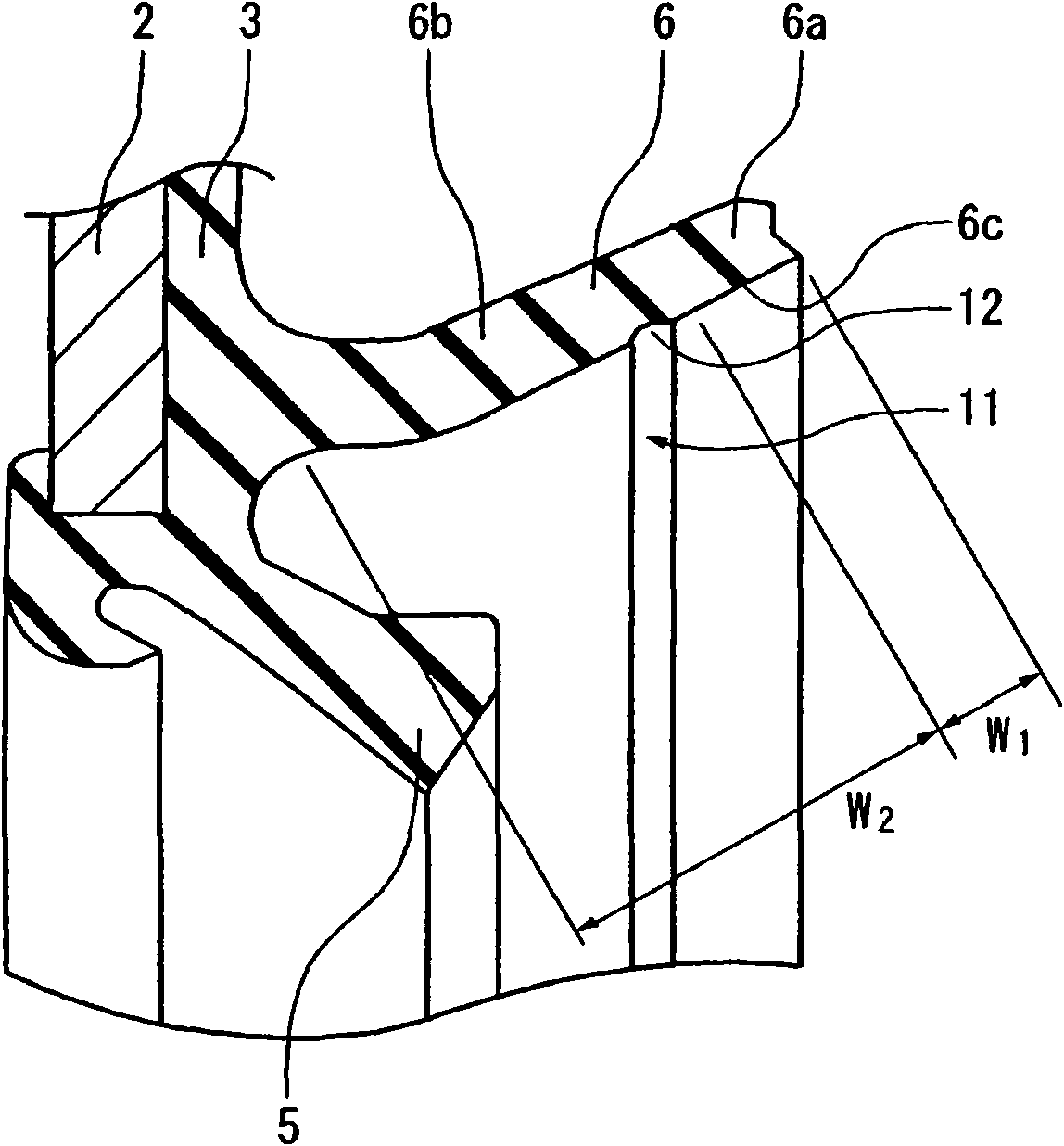
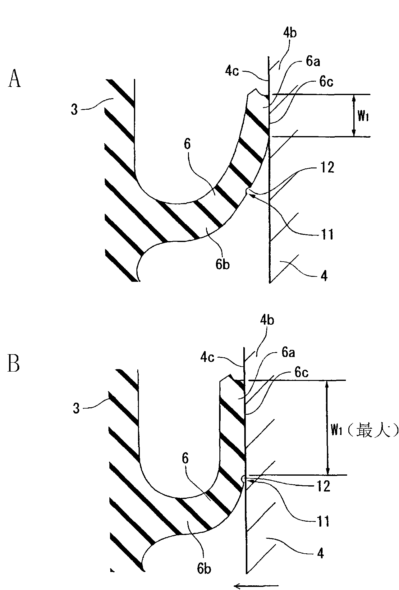
A hermetic sealing device having a side lip coming into slidable tight contact with a partner member such as a slinger in which contact state of the side lip can be stabilized and sliding resistance of the side lip can be reduced when lip tightening margin becomes maximum. The contact surface (6c) at the contact part (6a) of the side lip (6) has a cross-section of a straight shape in a free state. The noncontact part (6b) of the side lip (6) is provided with a grease holding portion (11) for holding grease being supplied to the contact part (6a). The grease holding portion (11) provided at the noncontact part (6b) of the side lip (6) is arranged at a position becoming the boundary between the contact part (6a) and the noncontact part (6b) when the width (W 1 ) of the contact part (6a) and lip tightening margin become maximum. The grease holding portion (11) consists of an annular groove (12) or a radial groove.

Description

technical field [0001] The present invention relates to seals and, more particularly, to seals having side lips. The sealing device of the present invention is used, for example, as a hub bearing seal (hub seal) in the fields related to automobiles, general machinery, and the like. Background technique [0002] Previously, as such a sealing device, there are known Figure 8 The sealing device 1 shown integrally has: a main lip 5, a rubber-like elastic body 3 bonded to the mounting ring 2 through vulcanization, and is slidably and tightly connected to the oil flinger ring as a sliding relative component The outer peripheral surface of the cylindrical portion 4 a of the (slinger) 4 and the side lip 6 are slidably closely connected to the axial end surface 4 c of the flange portion 4 b of the slinger 4 . [0003] The sealing device 1 having the above-mentioned structure can be tightly connected to the oil flinger 4 through the side lip 6 and the main lip 5 slidably, so as to e...

Claims


Application Information

Patent Timeline
IPC IPC(8): F16J15/32F16J15/3232
CPCF16J15/3264F16J15/324F16J15/32
Inventor 小林直人
Owner NOK CORP
Learn More