
Method and system for randomly switching alternating current

A switching system, alternating current technology, applied in the direction of electrical components, circuit devices, emergency power supply arrangement, etc., can solve the problems of increased circuit loss, power supply impact, long switching time, etc., to reduce power loss, prevent surge current, The effect of solving spike interference

Active Publication Date: 2009-12-09
OCEANS KING LIGHTING SCI&TECH CO LTD
View PDF0 Cites 27 Cited by
  • Summary
  • Abstract
  • Description
  • Claims
  • Application Information

AI Technical Summary

Problems solved by technology

[0002] The existing AC switching circuit adopts the voltage zero-crossing switching technology, which has the disadvantage of long switching intervals, that is, when the main AC power failure is detected, the logic controller sends a control signal to the solid-state zero-crossing switch. Switching is realized when the standby power crosses zero, and no transient peak interference is generated. The switching time depends on the phase difference between the main power and the backup power
In the existing AC zero-crossing switching circuit, the switching must wait until the voltage crosses zero to realize the switching, and the switching time is uncertain (depending on the phase difference between the main power supply and the backup power supply), and the switching time is too long (about 25ms), so that The circuit loss increases; at the same time, the switching time process will also bring high-frequency interference to the power supply, which will have a serious impact on the power supply of high-speed centralized circuits with high power requirements.

Method used

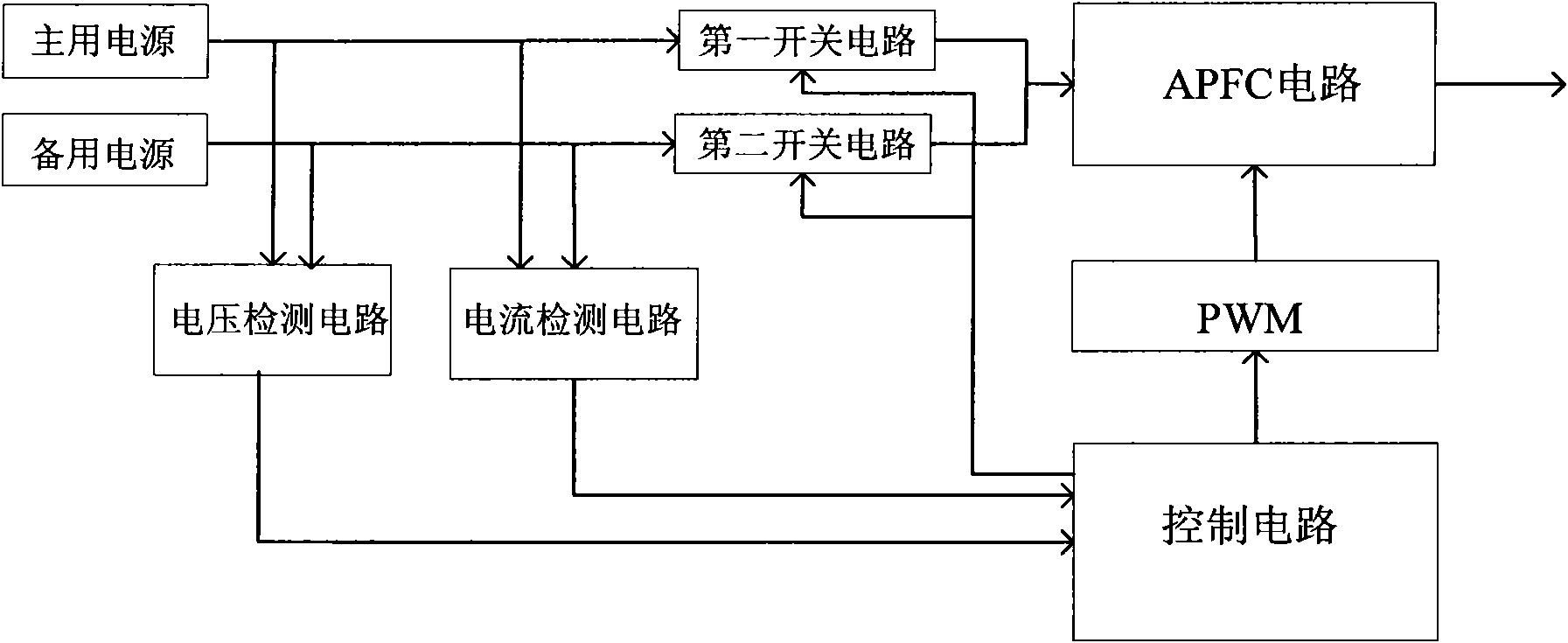
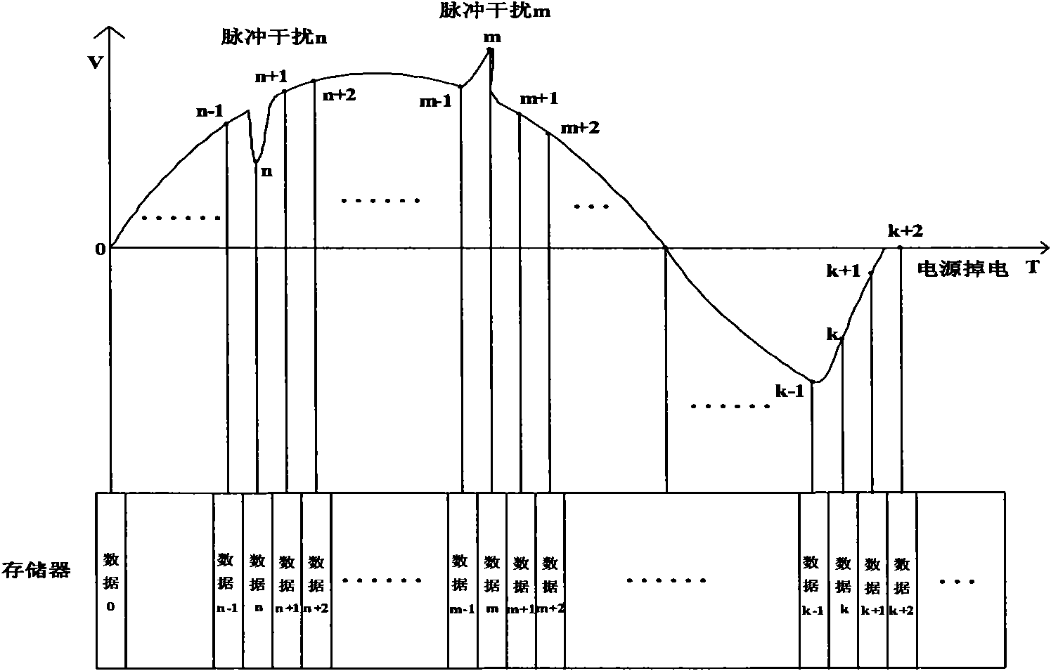
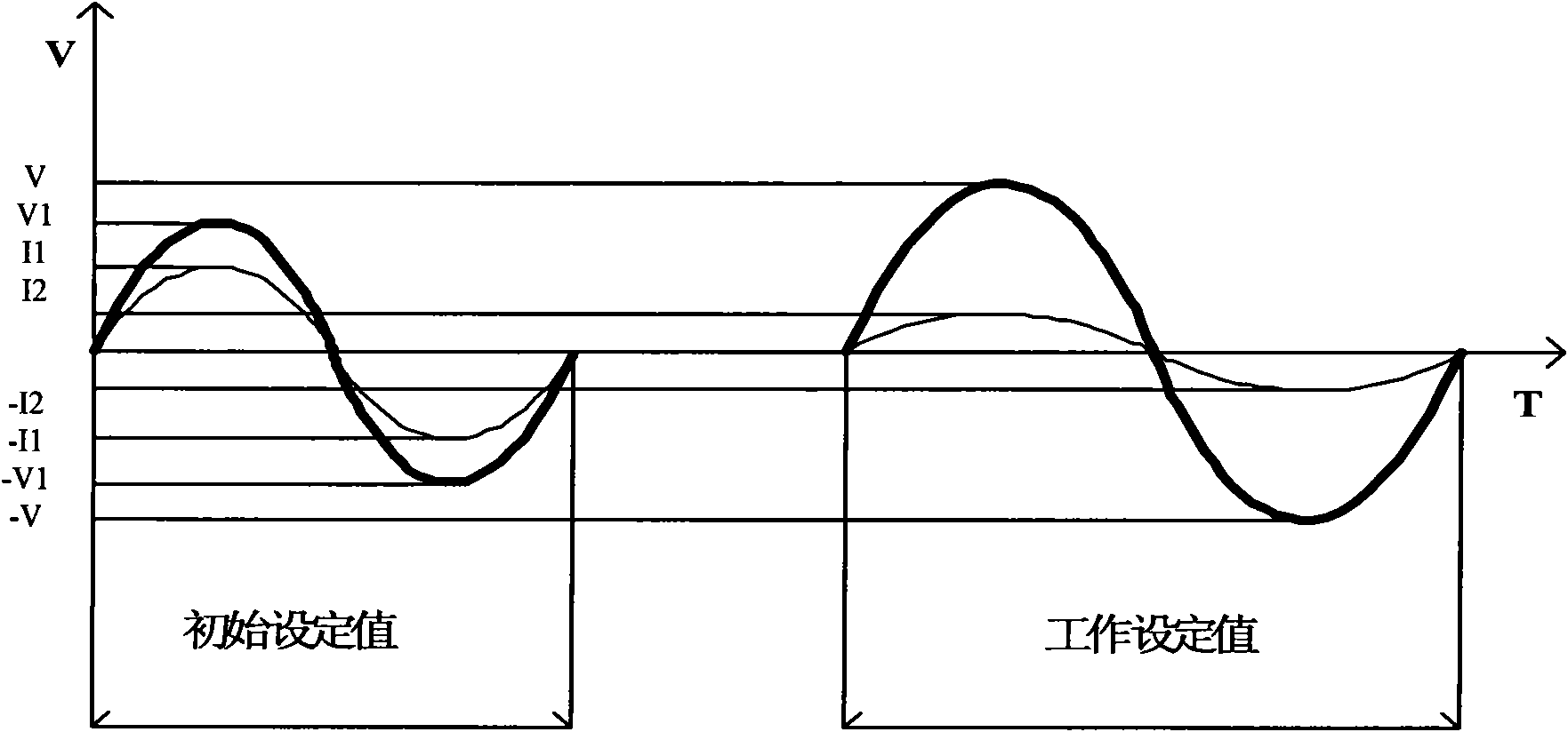

Image

  • Method and system for randomly switching alternating current
  • Method and system for randomly switching alternating current
  • Method and system for randomly switching alternating current

Examples


Embodiment Construction

[0027] The alternating current random switching method of the present invention comprises the following steps: S1, when the main power supply supplies power, detect the actual input voltage value V1 and the actual input current value I1 of the main power supply; S2, if the actual input voltage value V1 and its corresponding When the absolute value of the difference between the rated voltage exceeds a predetermined ratio (that is, greater than 50%), and / or the absolute value of the difference between the actual input current value I1 and its corresponding rated current value exceeds a predetermined ratio (that is, greater than 50%), Turn off the working power supply and turn on the standby power supply; S3. Calculate the initial current value I2 after switching according to the actual input voltage value V1 and the actual input current value I1, wherein the calculation formula of the initial current value I2 is: I2=V1*I1 / V, where V is the maximum value of the rated voltage of t...


PUM


Abstract

The invention relates to a method and a system for randomly switching alternating current. The system comprises a voltage detecting circuit, a current detecting circuit, a first switching circuit, a second switching circuit, a control circuit, a pulse width modulator (PWM) and an APFC circuit, wherein the first switching circuit is used for switching on or off a main power supply; the second switching circuit is used for switching on or off a reserve power supply; the control circuit is used for controlling the first switching circuit and the second switching circuit to switch on or off and transmitting a pulse signal to the PWM; the PWM is used for modulating an output dutyfactor according to the pulse signal transmitted by the control circuit; the APFC circuit is used for receiving the output dutyfactor of the PMW so as to control the output current, and thereby the linear rectification of the output current is realized to ensure the synchronization of the output voltage and the current phase of the APFC circuit. The state of the power supply can be automatically recognized by adopting the random switching so as to adapt to power supplies in different environments, and the switching time is greatly reduced and fixed. The current linear rectification can be randomly switched as alternating current to solve the peak interference brought by the random switching, and the power compensation is carried out to realize the minimum loss of circuit power.

Description

technical field [0001] The present invention relates to a power switching method and system, more specifically, to a random switching method and system for alternating current. Background technique [0002] The existing AC switching circuit uses the voltage zero-crossing switching technology, which has the disadvantage of long switching intervals, that is, when the main AC power failure is detected, the logic controller sends a control signal to the solid-state zero-crossing switch. The switching is realized when the standby power crosses zero, and no transient peak interference is generated. The switching time depends on the phase difference between the main power and the backup power. In the existing AC zero-crossing switching circuit, the switching must wait until the voltage crosses zero to realize switching, and the switching time is uncertain (depending on the phase difference between the main power supply and the backup power supply), and the switching time is too lon...

Claims


Application Information

Patent Timeline
Patent Type & Authority Applications(China)
IPC IPC(8): H02J9/00H02J9/06
Inventor 周明杰郑平张玉平
Owner OCEANS KING LIGHTING SCI&TECH CO LTD
Learn More