
Liquid metal infiltration visibility control method and special device thereof

A liquid metal and control method technology, which is applied in the direction of electrical program control, sequence/logic controller program control, etc., can solve the problems that the direct observation and online control of the liquid metal infiltration process cannot be realized.

Inactive Publication Date: 2009-12-09
NORTHWESTERN POLYTECHNICAL UNIV
View PDF1 Cites 10 Cited by
  • Summary
  • Abstract
  • Description
  • Claims
  • Application Information

AI Technical Summary

Problems solved by technology

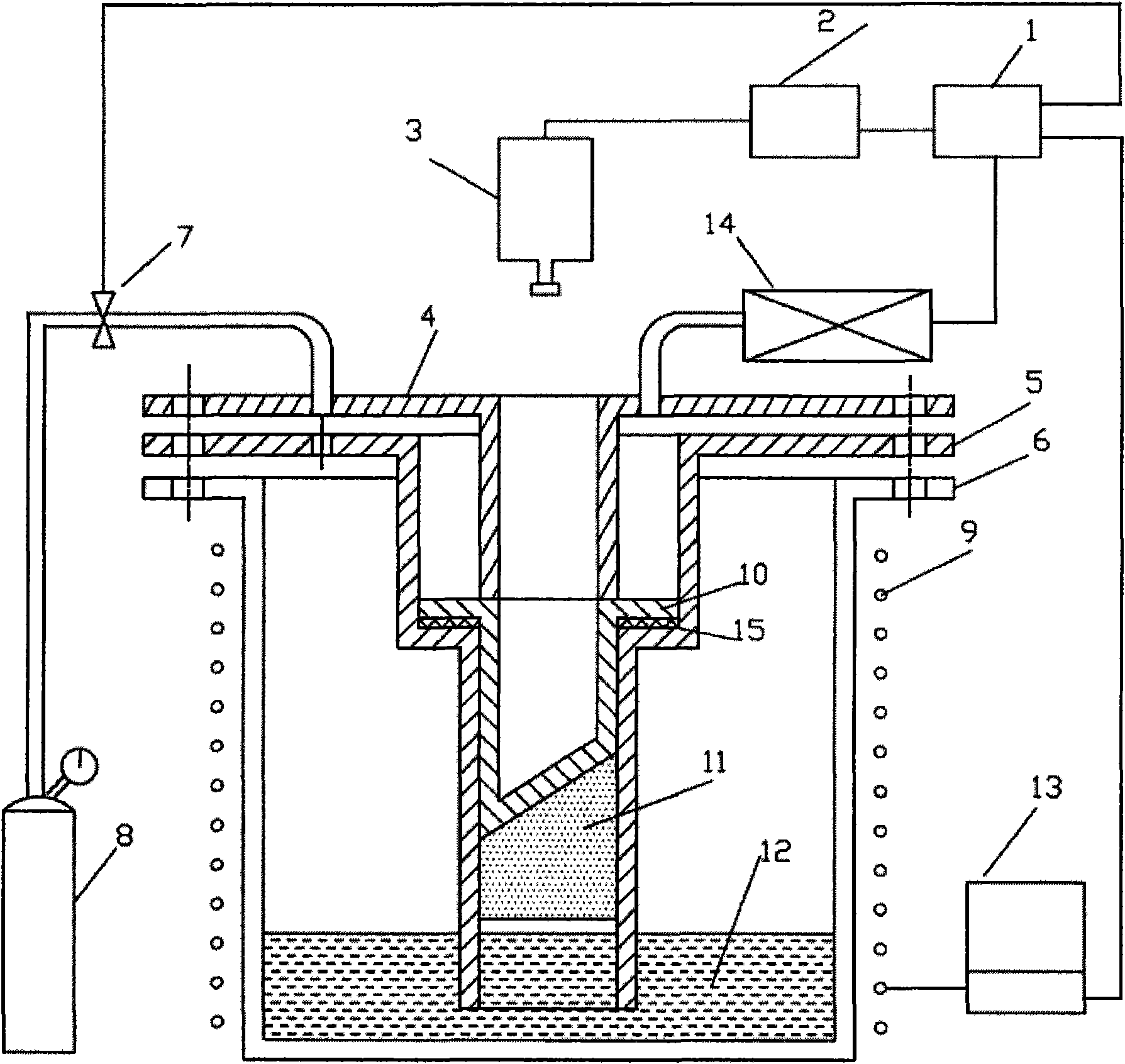
[0004] In order to overcome the deficiency that the prior art cannot realize the direct observation and on-line control of the impregnation process of the liquid metal in the porous medium prefabricated body, the present invention provides a liquid metal The visual control method of infiltration, which uses a special device for visualization of liquid metal infiltration in porous media, can realize real-time control of the infiltration process, and can intuitively obtain the temperature field of the infiltration process of liquid metal in porous media preforms Infrared thermal images of the distribution and flow regime of the infiltration front

Method used


Image

  • Liquid metal infiltration visibility control method and special device thereof
  • Liquid metal infiltration visibility control method and special device thereof
  • Liquid metal infiltration visibility control method and special device thereof

Examples


Embodiment 1

[0020] Embodiment 1: refer to figure 1 , a special device for visualization of liquid metal infiltration in porous media. The device is composed of: an impregnation control system 1 , an image acquisition and processing system 2 , an infrared thermal imager 3 , a temperature controller 13 , and a vacuum pumping system 14 . The infiltration system consists of the infiltration chamber cover 4 , the infiltration chamber 5 , the stainless steel crucible 6 and the sleeve 10 . Eight bolt holes are evenly distributed on the flanges of the infiltration chamber cover 4, the infiltration chamber 5 and the stainless steel crucible 6, and the three are connected by bolts. The seepage chamber cover 4 needs to press the sleeve 10 tightly, and the boss of the seepage chamber cover 4 has a through hole with the same size as the sleeve 10, so as to observe the temperature field information of the sleeve slope, wherein the bottom surface of the sleeve 10 is in the shape of a slope, The slope...

Embodiment 2

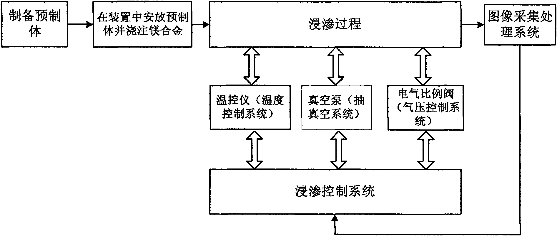
[0023] Embodiment 2: refer to figure 2 , Infrared thermal imager adopts Infortek VarioCAM hr head480 during the implementation of the method of the present invention, the base metal used is AZ91D magnesium alloy, and the prefabricated body is produced by Luoyang Refractory Research Institute. 2 o 3 Made of short fibers. Visualization method for liquid metal infiltration in porous media:

[0024] 1) Put the prepared slope preform into the impregnation chamber 5, put the AZ91D magnesium alloy into the stainless steel crucible 6, and seal the device;

[0025] 2) Start the temperature control system to heat for 1 hour, so that the temperature of the stainless steel crucible reaches 820±5°C, all the magnesium alloy is melted, and keep warm for 30-40 minutes;

[0026] 3) Start the vacuum system, use a vacuum pump to vacuum the inside of the seepage cavity, and stop vacuuming when the vacuum reaches 0.095MPa;

[0027] 4) Start the infrared thermal imager, transmit the digital si...


PUM


Abstract

The invention discloses a liquid metal infiltration visibility control method and a special device thereof. An image acquisition and processing system is used for observing variation condition of thermal-induced imagery on sleeve bevel during infiltration; by analyzing the thermal image, vacuum degree in crucible cavity can be changed by an infiltration control system under incomplete infiltration and input voltage value of an electric proportional valve can be regulated, so as to change gas pressure in crucible cavity; or a systemic temperature controller is used for increasing the temperature of metal liquid, so as to cause the infiltration to go smoothly and realize real-time control of infiltration. The invention utilizes a special device in which the infiltration of liquid metal in porous medium is visible and truly reflects flow status of liquid metal in porous medium prefabricated body, the infiltration control system realizes real-time control of the infiltration, and the image acquisition and processing system realized visible observation of the infiltration.

Description

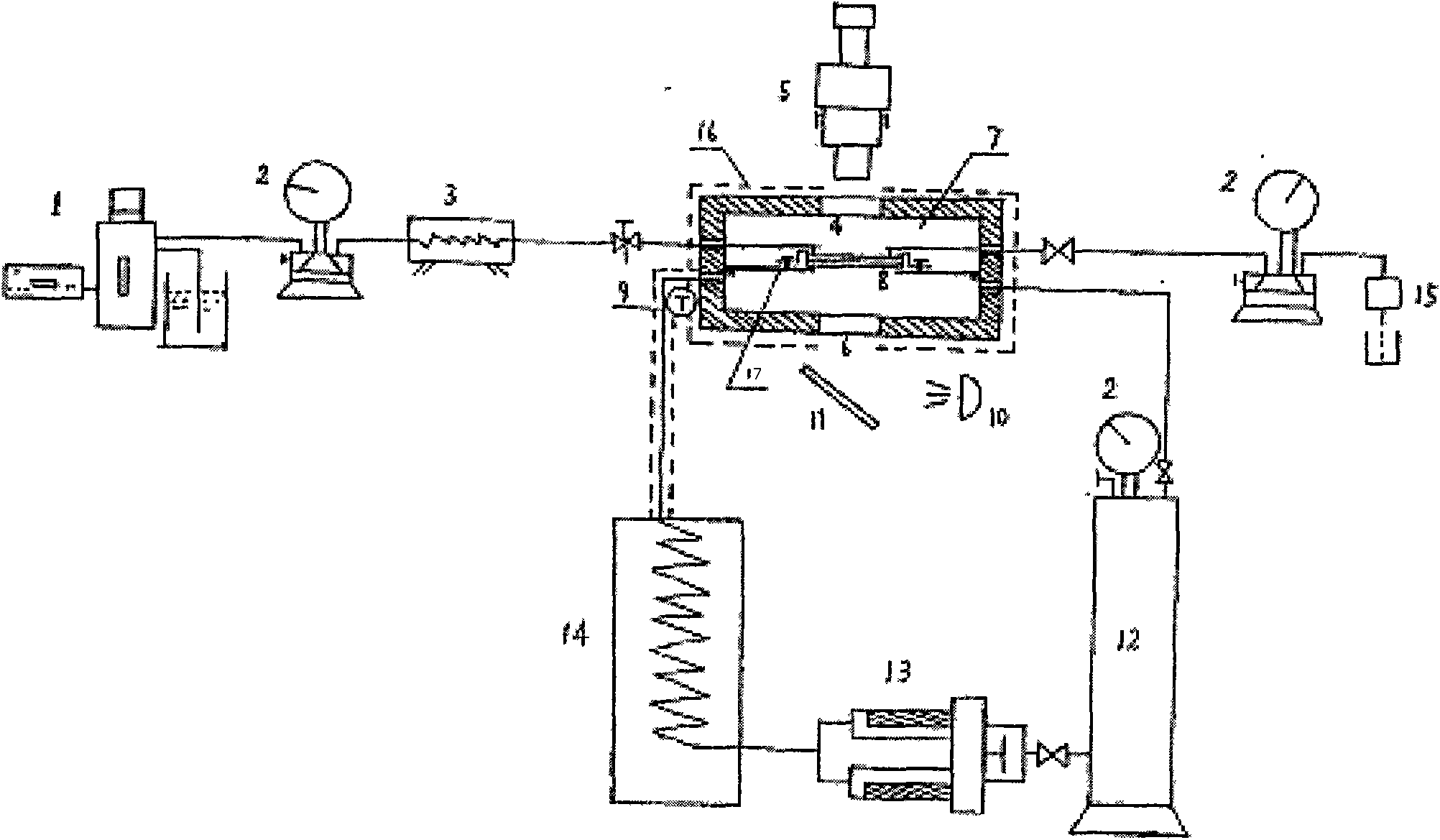
technical field [0001] The invention relates to a visualization control method, in particular to a visualization control method of liquid metal infiltration. It also relates to a liquid metal impregnation visualization control device. Background technique [0002] refer to image 3 , the document "Chinese Patent No. ZL 00242901.2" discloses a method for simulating seepage dynamics in porous media under high temperature conditions. An observation window 4 and an illumination window 6 are arranged on the top surface and bottom surface middle of the device used, a microscopic camera 5 is installed on the top of the observation window, a reflector 11 and a light source 10 are installed on the bottom of the illumination window, and a transparent micromodel 8 is used to simulate the porous medium pore structure and fix it in the observation room. The entrance and exit of the model are connected with the high-temperature container 3 outside the observation room, the micro-drive p...

Claims


Application Information

Patent Timeline
Patent Type & Authority Applications(China)
IPC IPC(8): G05B19/04C22C47/08
Inventor 齐乐华徐瑞周计明苏力争李贺军
Owner NORTHWESTERN POLYTECHNICAL UNIV
Learn More