Equipment and method for controlling laser light transmission

A laser emission and laser technology, applied in the field of lasers, can solve problems such as the inability to safely control the emission of lasers

Inactive Publication Date: 2011-03-30
北京市世嘉律师事务所
View PDF0 Cites 0 Cited by
  • Summary
  • Abstract
  • Description
  • Claims
  • Application Information

AI Technical Summary

Problems solved by technology

[0003] In order to overcome the defect that existing laser emitting equipment cannot safely control laser emission, the present invention proposes a device and method for controlling laser emission

Method used


Image

  • Equipment and method for controlling laser light transmission
  • Equipment and method for controlling laser light transmission
  • Equipment and method for controlling laser light transmission

Examples


Embodiment 1

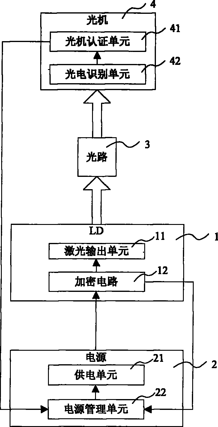
[0035] figure 1 is an embodiment of the laser device with security identification according to the present invention. In this embodiment, the laser device is a laser display device, and the laser used is a laser diode (LD), which is set in the laser display device. The laser display device includes: a laser diode (LD) 1 , a power supply 2 , an optical path 3 and an optical machine 4 .

[0036] Wherein, the laser diode (LD) 1 comprises a laser output unit 11 and an encryption circuit 12, the laser output unit 11 is used to generate and output laser light, the encryption circuit 12 is used to control the output of the laser output unit 11, and the encryption circuit 12 is provided with a Laser diode (LD) 1 corresponds to a unique power supply authentication code and a unique optical machine authentication code. The encryption circuit 12 is provided with a power supply interface and an encrypted data interface (not shown in the figure). The power supply interface is used to obta...

Embodiment 2

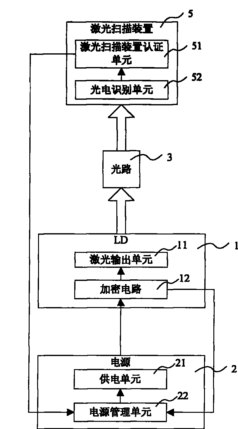
[0052] image 3 It is a structural schematic diagram of another embodiment of the laser device with security identification according to the present invention. Wherein, in this embodiment, the laser equipment is laser processing equipment, and the laser used is a laser diode (LD), which is set in the laser processing equipment. The laser processing equipment includes: a laser diode (LD) 1 , a power supply 2 , an optical path 3 and a laser scanning device 5 . The laser diode 1 includes a laser output unit 11 that generates laser light and outputs laser light and an encryption circuit 12 that controls the laser output unit 11. The encryption circuit 12 is provided with a unique power supply authentication code and a unique laser scanning code corresponding to the laser diode 1. Device authentication code, the encryption circuit 12 is provided with a power supply interface and an encrypted data interface (not shown in the figure).

[0053] The power supply 2 includes a power su...


PUM


Abstract

The invention relates to laser light transmission equipment comprising a laser, a power supply, a light path and a laser identification and authentication unit, wherein the laser is respectively connected with the power supply and the light path, is used for outputting a power authentication code to the power supply, and controls the laser light to be output to the light path according to the power supply; the power supply is used for receiving the power authentication code of the laser, authenticates the laser, controls current which is output to the laser, and ensures the laser to transmit laser light; the light path is used for laser transmission in the equipment; and the laser identification and authentication unit is used for receiving the authentication code corresponding to the laser light from the light path, determining that the authentication code is matched with the laser identification and authentication unit and adjusting the current which is output to the laser from the power supply. The invention ensures that the laser can realize high-power output only when the laser is arranged in the equipment matched with the laser and prevents the laser light with high-power output from being transmitted towards open space randomly.

Description

technical field [0001] The present invention relates to the technical field of lasers, and more particularly, the present invention relates to a device and method for controlling laser emission with security identification. Background technique [0002] The safe use of lasers has always been a concern of people. In order to prevent lasers from harming the human body, laser protective devices, such as protective glasses, are often used in laboratories. However, the problem of preventing people from intentionally using lasers to cause harm has been difficult to solve, especially if such lasers are small in size and high in output power, they are more likely to be held and cause injuries, and the problem becomes even more serious. For example, high-power and small-volume semiconductor lasers in laser emitting devices such as laser display devices and laser scanning devices, anyone can properly purchase these laser emitting systems and take out the semiconductor lasers separatel...

Claims


Application Information

Patent Timeline
Patent Type & Authority Patents(China)
IPC IPC(8): H01S3/10H01S5/06H01S3/09H01S5/042H01S3/00H01S5/00
Inventor 许江珂王斌石靖波贾中达
Owner 北京市世嘉律师事务所
Why Eureka
Try Eureka