
Touch panel, touch detection method thereof and display device with touch function

A touch panel and display device technology, applied in static indicators, data processing input/output processes, instruments, etc., can solve the problem that the thickness of the flat display device cannot be effectively reduced, and the thickness of the touch panel cannot be effectively reduced. , reduce the light transmittance of flat-panel display devices, etc., to achieve the effects of simple structure, low cost and high light transmittance

Active Publication Date: 2009-12-02
CHINA STAR OPTOELECTRONICS INT HK
View PDF0 Cites 8 Cited by
  • Summary
  • Abstract
  • Description
  • Claims
  • Application Information

AI Technical Summary

Problems solved by technology

However, the existing technology for integrating a touch panel into a flat-panel display device is generally to directly attach the touch panel to the flat-panel display device, and the sensing element used in the existing touch panel is composed of multiple layers of materials. Therefore, the thickness of the entire touch panel cannot be effectively reduced, and jointly, the thickness of the entire flat-panel display device cannot be effectively reduced.
Moreover, the touch panel also reduces the light transmittance and other optical performances of the flat-panel display device, thereby affecting the visual effect of the flat-panel display device.
[0004] In addition, most of the existing touch panels need to use planar printing technology or coating technology to install sensing elements with multi-layer materials on the entire touch panel, so it is difficult for manufacturers without planar printing or coating technology to enter the touch panel. control detection field

Method used


Image

  • Touch panel, touch detection method thereof and display device with touch function
  • Touch panel, touch detection method thereof and display device with touch function
  • Touch panel, touch detection method thereof and display device with touch function

Examples


Embodiment Construction

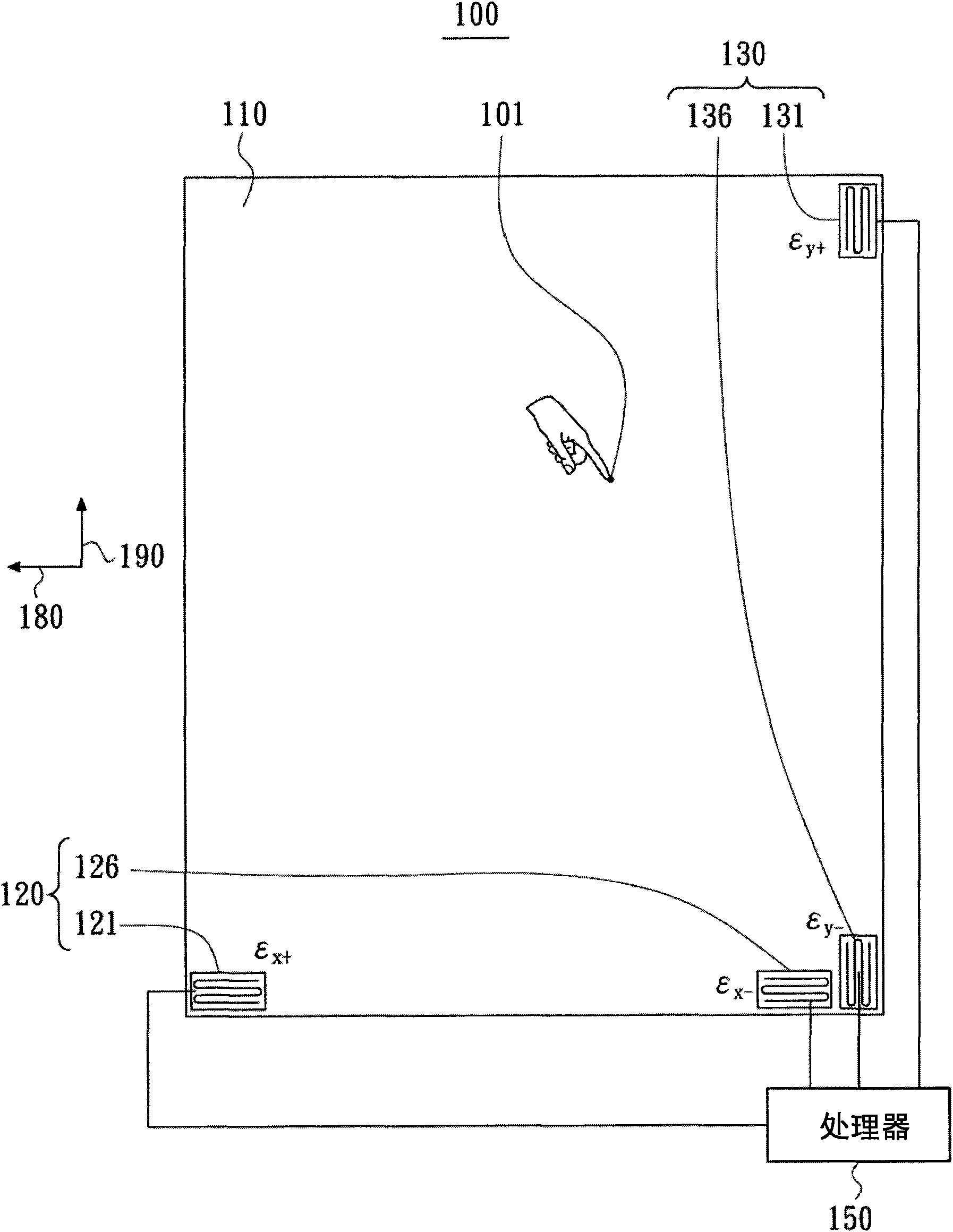
[0050] see figure 1 , which shows a schematic diagram of a touch panel 100 proposed by an embodiment of the present invention. The touch panel 100 is suitable for detecting a touch position of a touch point 101 generated by an object touching the touch panel 100 . The touch panel 100 includes a substrate 110 , at least one first direction detection device 120 , at least one second direction detection device 130 and a processor 150 . The first direction detecting device 120 is disposed on the first direction 180 (the X direction in this embodiment) of the substrate 110 to detect the first direction coordinate (X coordinate in this embodiment) of the touch point 101 . The second direction detection device 130 is disposed on the second direction 190 (the Y direction in this embodiment) of the substrate 110 to detect the second direction coordinate (Y coordinate in this embodiment) of the touch point 101 . The substrate 110 is a transparent substrate, such as a glass substrate. ...


PUM


Abstract

The invention discloses a touch panel, which is suitable for detecting the touch position of a touch point. The touch panel comprises a substrate and at least one first direction detection device. The first direction detection device is arranged in the first direction of the substrate to detect first direction coordinates of the touch point. Each first direction detection device comprises a first deformation induction device and a second deformation induction device. The first deformation induction device produces deformation in the first direction due to the production of the touch point, and provides a first variable due to the deformation; the second deformation induction device produces deformation in the first direction due to the production of the touch point, and provides a second variable due to the deformation; and the first direction coordinates are decided by the first variable and the second variable. The invention discloses a touch monitoring method for the touch panel and a display device with touch function at the same time.

Description

technical field [0001] The present invention relates to the field of touch detection, and in particular to a touch panel, a touch detection method thereof, and a display device with a touch function. Background technique [0002] With the advancement of technology, flat panel display devices (such as liquid crystal display devices) are widely used in mobile phones, notebook computers, desktops, etc. Consumer electronic products such as display devices and televisions have gradually replaced traditional cathode ray tube display devices and become the mainstream of display devices. [0003] The touch panel provides a new human-computer interaction interface, which is more intuitive and humane in use. Integrating the touch panel into the flat display device can replace the traditional input device, making it more direct and more humane. However, the existing technology for integrating a touch panel into a flat-panel display device is generally to directly attach the touch pan...

Claims


Application Information

Patent Timeline
Patent Type & Authority Applications(China)
IPC IPC(8): G06F3/041G02F1/133
Inventor 林彦夆侯皓元
Owner CHINA STAR OPTOELECTRONICS INT HK
Learn More