
Method for manufacturing disc brake seat

A production method and technology for a brake disc seat, applied in the direction of brake parts, etc., can solve the problems of increased manufacturing cost, complicated mold design, long production cycle, etc., and achieve the effects of stable production process, overcoming waste of raw materials, and shortening production cycle.

Active Publication Date: 2009-12-02
江苏威鹰机械有限公司
View PDF0 Cites 5 Cited by
  • Summary
  • Abstract
  • Description
  • Claims
  • Application Information

AI Technical Summary

Problems solved by technology

In order to adapt to various types of vehicles, a two-piece disc brake seat structure has emerged, which is composed of a disc brake disc and a fixing seat. The shape and structure of the disc brake disc and the fixing seat can be designed according to the installation needs of the working conditions. There are axle holes and screw holes on the disc brake disc, and there are also axle holes and screw holes on the fixing seat. When matching with different types of vehicles, you only need to replace the fixing seat of different sizes, and then fix the fixing seat on the The screw holes of the disc brake disc are used to facilitate assembly and save costs. Generally, the disc brake disc seat is produced by machining or casting. The machining method to produce the disc brake disc seat has the advantage of high precision, but its production cycle Long, high manufacturing cost; the casting method produces the disc brake seat, the mold design is complicated, which increases the manufacturing cost
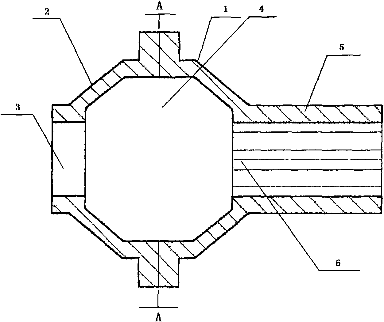
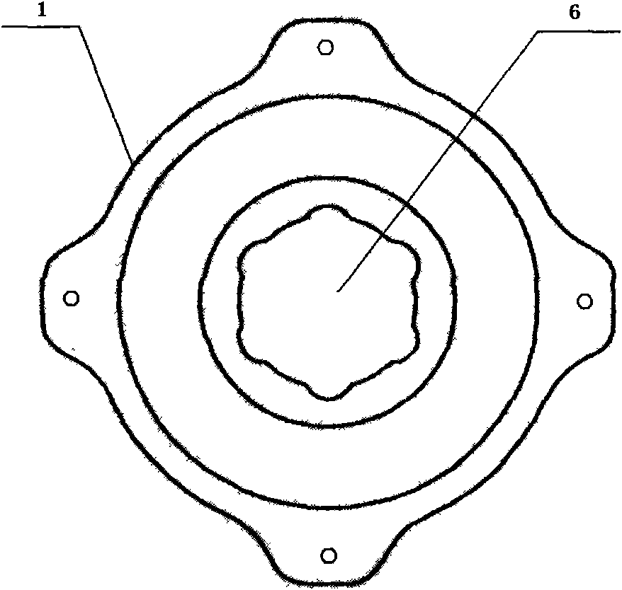
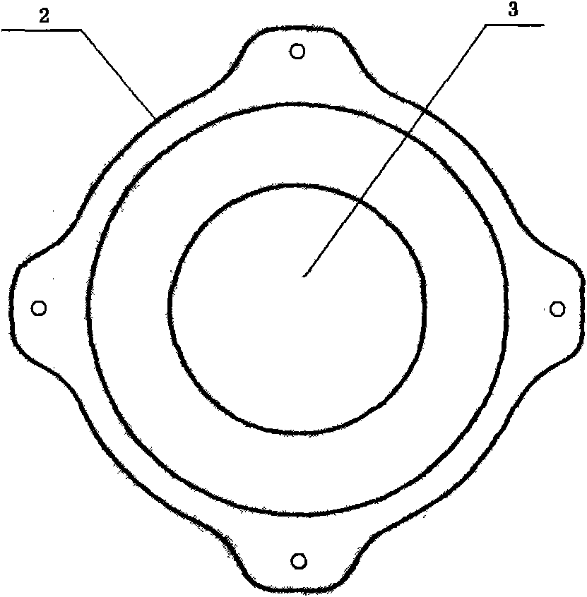
Our company has designed a disc brake disc seat, which is produced by machining or casting. Not only the production cycle is long, but also the manufacturing cost is high. It is composed of a disc brake disc and a fixing seat. screw hole and shaft hole, the shaft hole on the fixed base is a circular structure, the disc brake disc can be screwed on the fixed base, a cavity is provided between the disc brake disc and the fixed base, and the disc brake disc The shaft hole of the brake disc is connected to the liner. The disc brake disc and the liner are integral structures. The shaft hole of the disc brake disc and the inner hole of the liner are evenly distributed in the shaft hole by six sections of arc surface, forming six fairways

Method used


Image

  • Method for manufacturing disc brake seat
  • Method for manufacturing disc brake seat
  • Method for manufacturing disc brake seat

Examples


Embodiment Construction

[0022] The technical solutions of the present invention will be further specifically described below through the embodiments and in conjunction with the accompanying drawings.

[0023] figure 1 , figure 2 and image 3 Shown is an embodiment of a disc brake disc seat produced by the present invention. A disc brake disc seat is composed of a disc brake disc 1 and a fixing seat 2. The disc brake disc and the fixing seat are provided with screw holes and shaft holes. The shaft hole 3 on the fixing seat is a circular structure. The disc brake disc 1 can be screwed on the fixing seat 2, and a cavity 4 is arranged between the disc brake disc 1 and the fixing seat 2, and the shaft hole 6 of the disc brake disc 1 is connected to the liner 5, and the The disc brake disc and the liner are integral structures, and the shaft hole 6 of the disc brake disc 1 and the inner hole of the liner 5 are evenly distributed in the shaft hole by six sections of arc surfaces, forming six ballways. ...


PUM


Abstract

The invention discloses a method for manufacturing a disc brake seat by forging technology, which contains the manufacturing methods of a disc brake plate and a fixed seat. The manufacturing method of the disc brake plate comprises the following steps: baiting, ball blasting, heating, upsetting, extrusion, inversely extruding, annealing, ball blasting, parkerising, saponifying, sole sawing and cold finishing. In the method, the warm extrusion technology is adopted to carry out metal volume distribution, thus not only overcoming waste of raw materials in the prior art, reducing manufacturing costs but also shortening production period and having stable manufacturing technique.

Description

technical field [0001] The invention relates to a production method of a disc brake disc seat, in particular to a method for producing a disc brake disc seat by forging technology. Background technique [0002] The positioning mechanism of the existing ATV rear axle mainly consists of a liner, a rear axle housing, a disc brake disc seat, a chain wheel disc seat, a left connecting disc, and a right connecting disc. The rear axle housing is installed between the sprocket disc seat and the disc brake disc seat. There is a bearing at both ends of the rear axle housing respectively, and the bearing is positioned by the liner in the rear axle housing. A liner is respectively added between the left connecting disc and the sprocket disc seat and between the right connecting disc and the disc brake disc seat. In order to adapt to various types of vehicles, a two-piece disc brake seat structure has emerged, which is composed of a disc brake disc and a fixing seat. The shape and stru...

Claims


Application Information

Patent Timeline
Patent Type & Authority Applications(China)
IPC IPC(8): F16D65/04
Inventor 张太良
Owner 江苏威鹰机械有限公司
Learn More