
Partitioned saving type water supply heating device

A heating device and energy-saving technology, which is applied in the field of partition-saving water supply heating devices, can solve problems such as imperfect design, single water outlet structure, and unscientific structure setting, and achieve the effect of wide application range and compact structure design

Active Publication Date: 2018-10-09
苏州果汁网信息科技有限公司
View PDF6 Cites 0 Cited by
  • Summary
  • Abstract
  • Description
  • Claims
  • Application Information

AI Technical Summary

Problems solved by technology

[0002] The water supply device is suitable for schools, hotels, bathing saunas, government agencies, factories, hospitals and other places that require a large amount of domestic water. There are various problems during use
[0003] In order to solve the above-mentioned problems, the present invention is proposed, which overcomes the problems of the current water supply device, such as the waste of the water outlet and the low efficiency of water receiving due to the complete separation of cold and heat, and solves the problems of the current water supply device. The water flow structure causes problems such as uncontrollable water temperature or inaccurate control, which improves the current water supply device. Since the incoming water is not purified and the structure of the outgoing water is single, the use scene is small, which makes the present invention have a compact structure design. Pre-purification, instant heating, mixed temperature control, wide application range, etc.

Method used


Image

  • Partitioned saving type water supply heating device
  • Partitioned saving type water supply heating device
  • Partitioned saving type water supply heating device

Examples


Embodiment Construction

[0018] The following will clearly and completely describe the technical solutions in the embodiments of the present invention with reference to the accompanying drawings in the embodiments of the present invention. Obviously, the described embodiments are only some, not all, embodiments of the present invention. Based on the embodiments of the present invention, all other embodiments obtained by persons of ordinary skill in the art without making creative efforts belong to the protection scope of the present invention.

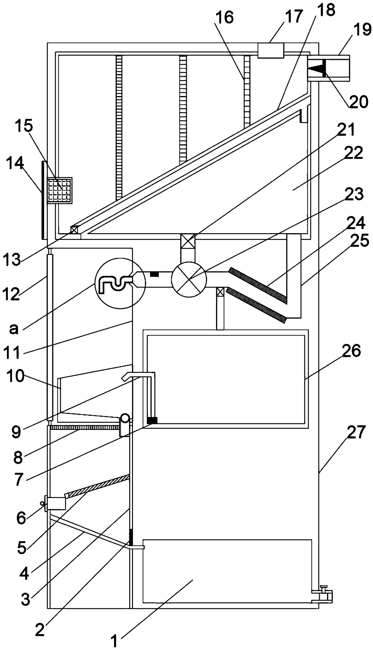
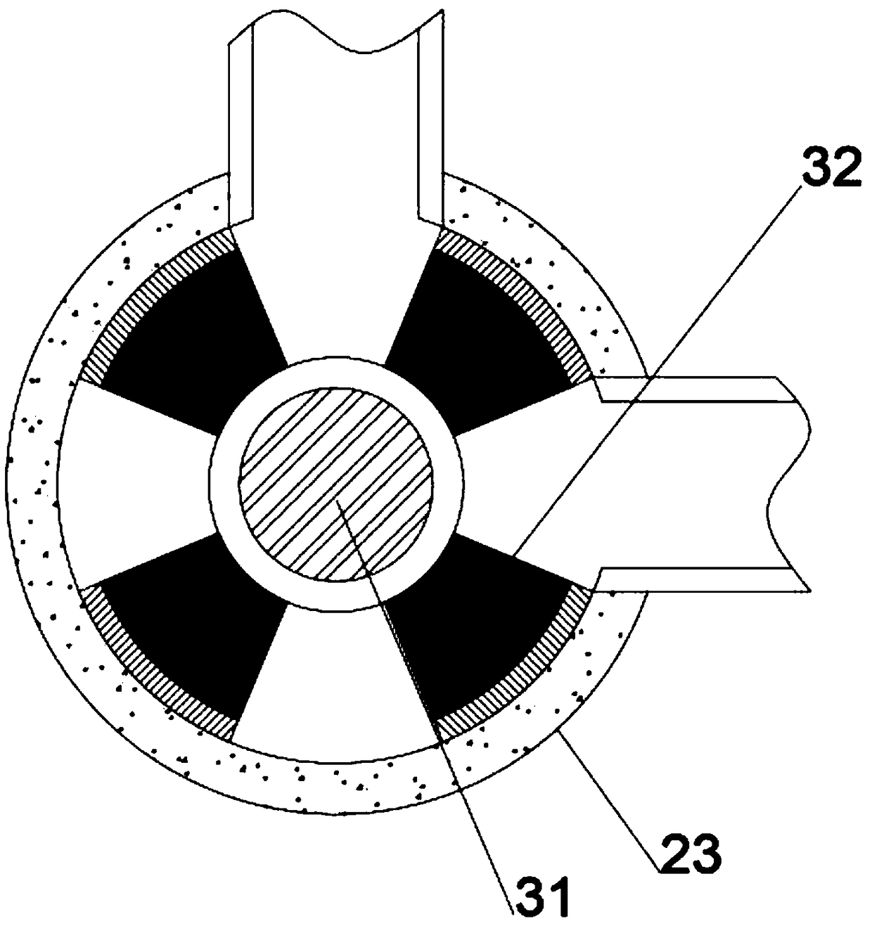
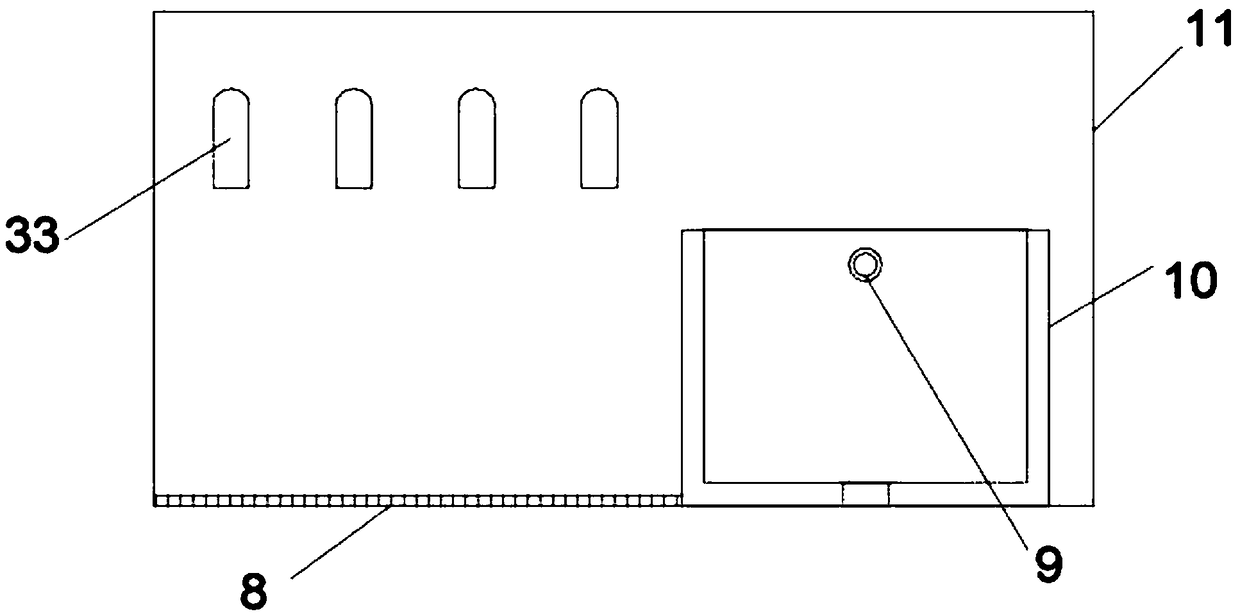
[0019] see Figure 1~4 , in an embodiment of the present invention, a partition-saving water supply heating device includes a vertical heat preservation installation cover 27, and an inclined bottom liquid inlet tank 18 is horizontally arranged inside the upper end of the heat preservation installation cover 27, and the inclined bottom liquid inlet The upper end of the box 18 is horizontally and equally spaced and vertically provided with three groups of filte...


PUM


Abstract

The invention discloses a partitioned saving type water supply heating device. The partitioned saving type water supply heating device comprises a vertical heat insulation mounting cover; a slope bottom liquid inlet tank is horizontally arranged in the upper end of the heat insulation mounting cover; a slope top liquid storage tank is horizontally arranged in the position, on the lower right portion of the slope bottom liquid inlet tank, of the heat insulation mounting cover; a slope diversion hole is formed between the slope top liquid storage tank and the slope bottom liquid inlet tank in anembedded mode; an electromagnetic valve is arranged at the position, communicating with the left end of the slope diversion hole, of the lower left corner of the slope bottom liquid inlet tank; a diversion pipe is arranged at the position, communicating with the right end of the slope diversion hole, of the upper right corner of the slope top liquid storage tank; a water outlet working cavity isformed in the middle of the heat insulation mounting cover in a leftwards concaved mode; and a rotary gate is installed at the position, matched with the water outlet working cavity, of the left sideof the heat insulation mounting cover through a vertical rotary shaft. The partitioned saving type water supply heating device has the advantages of being compact in structural design and wide in application range, achieving purifying in advance, achieving instant heating and mixed temperature control water outlet, and the like.

Description

technical field [0001] The invention relates to the field of energy-saving equipment, in particular to a zone-saving water supply heating device. Background technique [0002] The water supply device is suitable for schools, hotels, bathing saunas, government agencies, factories, hospitals and other places that require a large amount of domestic water. There are various problems during use. [0003] In order to solve the above-mentioned problems, the present invention is proposed, which overcomes the problems of the current water supply device, such as the waste of the water outlet and the low efficiency of water receiving due to the complete separation of cold and heat, and solves the problems of the current water supply device. The water flow structure causes problems such as uncontrollable water temperature or inaccurate control, which improves the current water supply device. Since the incoming water is not purified and the structure of the outgoing water is single, the...

Claims


Application Information

Patent Timeline
IPC IPC(8): F24D17/00F24D19/00
CPCF24D17/00F24D19/00
Inventor 杨康
Owner 苏州果汁网信息科技有限公司
Learn More